
Data Logger with Serial Interface

The data logger circuit is designed to provide a reliable means of signal amplification and digitization, allowing for the integration of various sensor types. The use of dual voltage levels (12V for the op-amps and 5V for the digital components) is critical in ensuring compatibility and functionality across different parts of the system. The choice of the PIC16F688 microcontroller is appropriate due to its capabilities in processing analog signals and communicating via serial protocols.
The operational amplifier (op-amp) configuration is pivotal in ensuring that the input signals are adequately amplified before reaching the microcontroller. The selection of trimmer potentiometers (R1 and R10) allows for fine-tuning of the signal levels, which is essential for maintaining accuracy in sensor readings. The LED indicator (LED1) serves not only as a visual feedback mechanism but also assists in the calibration process by providing real-time information on signal levels.
The voltage divider network formed by resistors R5, R6, and R7 is a critical safety feature that protects the microcontroller from over-voltage conditions, thereby enhancing the longevity and reliability of the circuit. The overall design emphasizes flexibility and user-friendliness, allowing for easy integration of various sensors and straightforward adjustments to accommodate different operational conditions. The serial communication facilitated by the MAX232 driver ensures that the digitized data can be easily transmitted and logged on a computer, making this data logger a versatile tool for various applications in data acquisition and monitoring systems.The data logger consists of a simple op-amp amplifier circuit that amplifies the signal and sends it to be digitized by a PIC16F688 microcontroller, serialized, and sent to the computer`s serial port via a MAX232 serial driver: I guess you are already wondering about some of the unusual arrangmenents in the analog part in the schematic diagram abo ve. Part of it is because of the voltage differences between the analog and digital part: the op-amps work on 12V while the microcontroller and the serial driver require 5V. Part of it is to make the different kind of sensors I plan to use easier to connect. Finally, this is partly because I`m really lazy and when I got the things to work to my satisfaction I refused to change anything.
The point is - unusual or not, it works. IN1 is a DC-input with a range of 1-11V. Whatever voltage is applied to IN1 is directly passed to the amplifier. Try to keep the voltage centered around the 6V point for best results. IN2 is an AC (self-centering) input with a range of ±5V. The trimmer potentiometer R1 connected to this input centers the signal at 6V when the sensor signal is not changing. Switching between inputs is done by shorting the JP1 jumper. You can either use a switch there and do this manually, or wire JP1 into the connectors you use to plug-in your sensors (which is the way I did it).
Before finishing with the input part, notice the optional amplifier OP2 in the lower part of the diagram. Some sensors based on a voltage divider work best when the voltage is split close to the half point - in other words, if you have a resistor/photoresistor bridge and in the particular conditions the photoresistor has 10k resistance, the signal will be stronger if the other resistor in the bridge is also around 10k.
Use the trimmer potentiometer R10 to set the desired center point. Afterwards, LED1 will switch on and off when the center point is crossed, helping you adjust your sensor correspondingly. Amplification is controlled by adjusting R4. If you wish, you can use a higher value for this potentiometer - this will give you higher amplification, but at the cost of more noise.
The output from OP1 is passed to the microcontroller through the voltage divider composed of R5, R6, and R7. The voltage divider is here to assure that the signal passed to the analog input AN4 never goes above 5V.
Before plugging in the microcontroller, adjust R6 so when the output from OP1 is at it`s top range, the voltage out of R1 is just below 5V. The PIC16F688 microcontroller digitizes the signal from AN4, applies checksum information and passes the serialized data at 1200 bps to the MAX232 serial driver.
From there, it`s just a matter of plugging a serial cable in your computer and running the logger script logger. pl to record the data. 🔗 External reference
Related Circuits

This project utilizes a standard Hitachi HD44780 (or compatible) controller chip to operate an LCD display using only two wires. Various shapes and sizes are available, including standard line lengths of 8, 16, 20, 24, 32, and 40 characters...
This week, there was a Southern theme in anticipation of Spring Break, leading to the decision to build a LassoBot. This robot throws a lasso in a circular motion until it captures an object in its path. Once an...
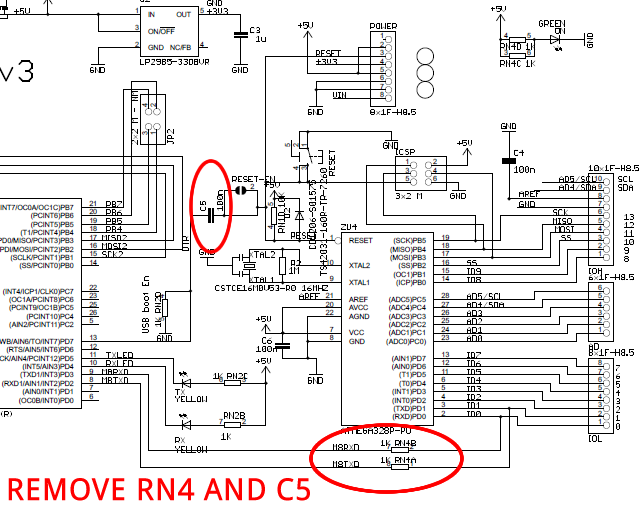
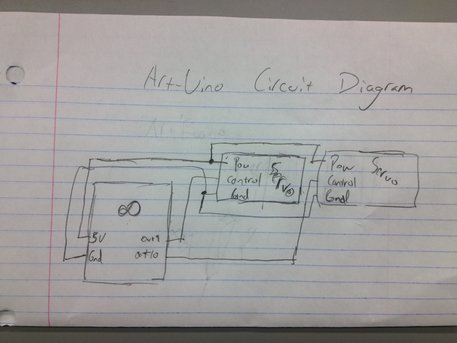
The Arduino Uno is a simple modification that bypasses the USB circuitry, allowing the device to be programmed using a serial port. The Arduino Uno is a widely used microcontroller board based on the ATmega328P microcontroller. It is designed to...
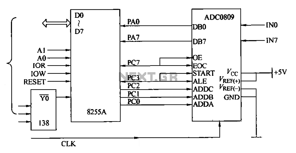
The ADC0809 is an 8-channel analog switch integrated with an 8-bit successive approximation analog-to-digital (A/D) converter. It supports the selection of eight input channels through address latch and encoder channel selection signals ADDA, ADDB, and ADDC. The address latch...
I designed a simple sinewave generator based on a Analog Devices AD9832 chip. It will generate a sinewave from 0.005 to 12 MHz in 0.005 Hz steps. That's pretty good, and definitely good enough for me! But while waiting...
This smartcard adapter follows exactly the specification ISO 7816. Also, the protocol is the "asynchronous half duplex T=0 protocol" with "active low reset" and "inverse convention" as defined in this standard. The following description may be used in order...