
Data Receiver

The A3018 Data Receiver is a critical component in systems that require reliable data transmission in the presence of potential radio-frequency interference. The use of shielded LWDAQ cables is essential to mitigate the effects of electromagnetic interference, which can corrupt data integrity. The design of the A3018 allows it to function effectively in conjunction with various subcutaneous transmitters, ensuring accurate data collection.
The internal architecture of the A3018 integrates multiple functionalities, including RF signal reception, demodulation, and data recording. The logic chip is tasked with decoding incoming RF signals, while the 512 kBytes RAM provides ample storage for incoming messages. The incorporation of a demodulator and RF amplifier enhances the receiver's ability to process weak signals, ensuring effective data capture even in challenging environments.
The presence of indicator LEDs serves a dual purpose: they provide immediate feedback to users regarding the operational status of the device and assist in troubleshooting by indicating specific conditions such as power status, buffer status, and data upload activity. The design considerations ensure that the A3018 operates seamlessly within a larger system, facilitating efficient data management and communication with external devices like laptops through a TCP/IP connection.
Overall, the A3018 Data Receiver exemplifies a well-engineered solution for capturing and recording data under conditions where traditional Ethernet connections may falter, thereby reinforcing its utility in advanced electronic applications.Always use shielded LWDAQ Cable to connect the A3018 to the LWDAQ Driver, not Ethernet cables. The shielding stops the cable acting like a radio-frequency antenna. The correct wiring gives the data transfer more immunity to static discharge, as we discuss below. The A3018A, A3018B, and A3018C have a bug in their firmware that ca uses them to record an excessive number of bad messages in the presence of radio-frequency interference. In particular, these devices cannot share a LWDAQ Driver with an RF Spectrometer ( A3008 ), because the spectrometer`s local oscillator interferes with SCT message reception.
Return the A3018 to us for a free tune-up and upgrade to A3018D. The Data Receiver (A3018) receives messages from transmitters such as the Subcutaneous Transmitter ( A3013 ) and Subcutaneous Transmitter ( A3009 ). The A3018 is an example of a data recorder, as used with the Recorder Instrument. The A3018 records messages in a first-in first-out buffer. You read out the buffer with LWDAQ hardware and a TCPIP connection. Figure: Data Receiver (A3018C) in a SCT System. The A3018C is the silver box with the big red letters on it. A black coaxial cable carries the antenna signal to the Data Receiver. A white, shielded LWDAQ cable connects the Data Receiver to the LWDAQ Driver. A blue ethernet jumper cable connects the LWDAQ Driver to the laptop. The A3018 receives RF signals through a cable-mounting antenna, such as the A3015. A BNC socket on the side of the A3010 enclosure provides connection for the antenna. The LWDAQ connection is through an RJ-45 socket on the opposite side from the antenna. There are four indicator LEDs next to the RJ-45 socket. The green one closest to the socket is the power indicator (Power). The red LED shines when the message buffer is empty (Empty). The orange LED shines when the A3018 is uploading messages from the buffer to the LWDAQ driver (Upload).
The far green LED shines when the A3018 is storing messages in the buffer (Receive). Figure: Data Receiver (A3018C) Interior. The lid of the enclosure is off, and you can see the separate circuits, joined by cables. Shown are (1) LWDAQ device socket, (2) Antenna input, (3) Logic chip that decodes incoming RF data, (4) 512 kBytes RAM to store messages, (5) Aluminum box, (6) Demodulator, (7) RF Amplifier, (8) Mixer to downshift RF to IF, (9) 65-MHz Low-Pass Filter to extract IF, (10) Local Oscillator 864 MHz for downshifting RF to IF, (11) Limiting Amplifier. The A3018 combines three circuits, as shown in the picture above. The RF input passes to a Demodulating Receiver ( A3017 ). The A3017 receives its local oscillator input from a SAW Oscillator ( A3016SO ). The demodulated output of the A3017 connects to a Data Recorder ( A3007 ). 🔗 External reference
Related Circuits
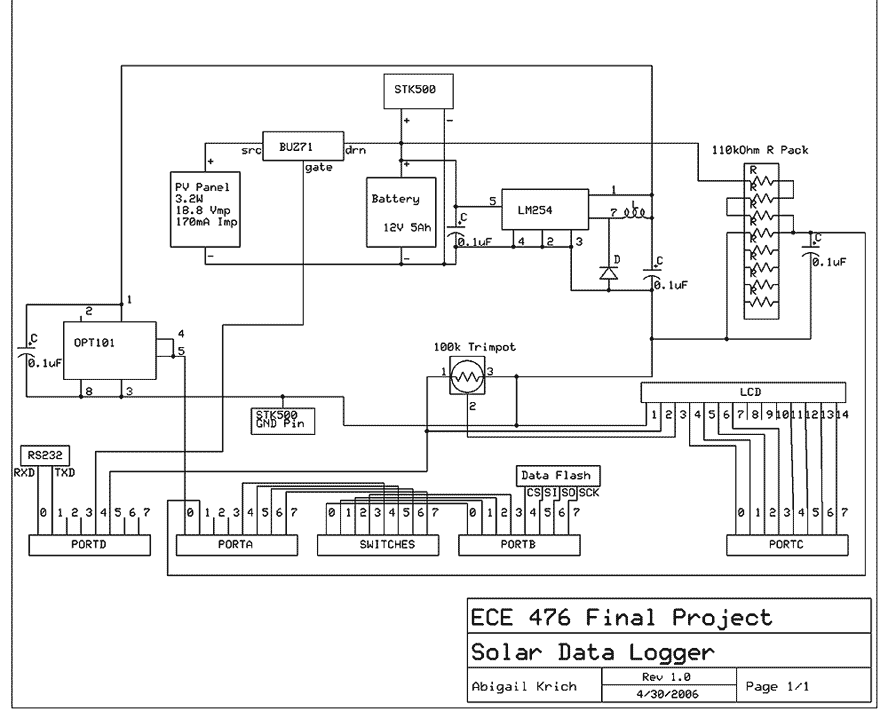
My project is a self-powered solar data logger. Put out in the sunlight, it will measure the light level and log this to memory to be later downloaded to a computer. The system is powered by a small solar...
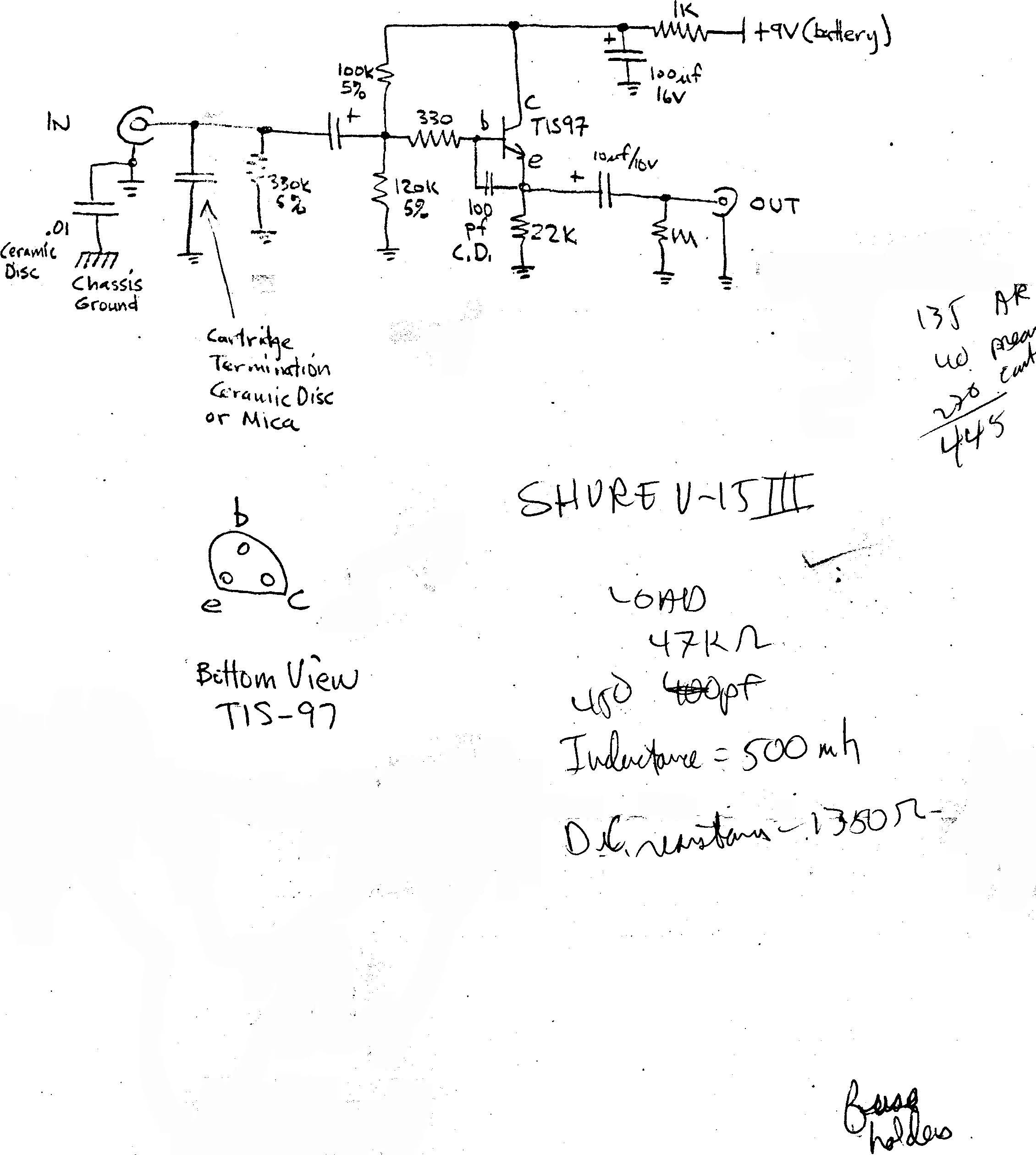
The infrasonic filter was a particularly useful feature of the phono preamp. Instructions were provided on how to build an external buffer circuit to use with any phono preamp, in order to avoid cartridge impedance interaction. A letter was...
Many audio systems consist of separate units, and due to economic reasons, only the amplifier is equipped with a remote control receiver module. Control signals are then transmitted to other units using patch cables. For instance, the tuner and...
This is a simple RF receiver mainly for low-distance digital radio receiver application. The analog output of this circuit should be connected to a schmitt-trigger signal conditioning circuit with a proper value capacitor (from collector of T3). L1 for...
This receiver is designed around the widely used ZN414 integrated circuit, which covers the medium wave band from approximately 550 to 1600 KHz. The coil and tuning capacitor can be salvaged from an old medium wave radio to expedite...
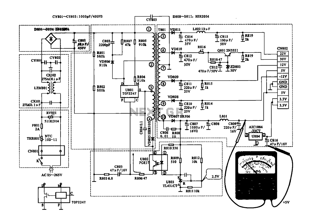
The Coship CDVB3188V receiver features a switching power supply circuit similar to the CDVB3188C model. The circuit includes several key components: an AC input circuit, an anti-jamming filter circuit, a complete flow filter circuit, and a switching oscillation circuit....