
Superregenerative receiver

The RF receiver circuit described is designed for low-distance digital radio applications, operating at a frequency of 27 MHz. The primary function of this circuit is to receive radio frequency signals and convert them into a usable analog output.
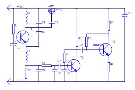
The circuit includes an RF front-end that typically consists of a tuned circuit, which is formed by the inductor L1. This inductor is specified to have approximately 10 turns and a diameter of 6 mm, which is crucial for achieving the desired resonant frequency. The inductance value should be calculated based on the resonant frequency formula, considering the capacitance used in conjunction with L1 to ensure proper tuning to 27 MHz.
The output from the RF receiver is an analog signal that may contain noise and fluctuations. To improve the quality of this signal, it is recommended to connect the output to a Schmitt trigger signal conditioning circuit. This circuit will provide clean digital output by converting the analog signal into a square wave, effectively removing any noise. The Schmitt trigger utilizes hysteresis to ensure that the output transitions cleanly between high and low states, preventing false triggering due to noise.
In addition, a capacitor of an appropriate value should be placed at the collector of transistor T3, which is part of the amplification stage of the RF receiver. The capacitor will help filter the output signal, smoothing out any variations and ensuring stable operation.
Overall, this simple RF receiver design is suitable for applications requiring short-range digital radio communication, and its performance can be optimized through careful selection of component values and circuit configuration.This is a simple RF receiver mainly for low-distance digital radio receiver application. The analog output of this circuit should be connected to a schmitt-trigger signal conditioning circuit with a proper value capacitor (from collector of T3). L1 for 27Mhz is about 10 turns, 6 mm diameter coil body. 🔗 External reference
Related Circuits
This is a simple RF receiver primarily designed for low-distance digital radio receiver applications. The analog output of this circuit should be connected to a Schmitt-trigger signal conditioning circuit with an appropriate capacitor value (from the collector of T3)....
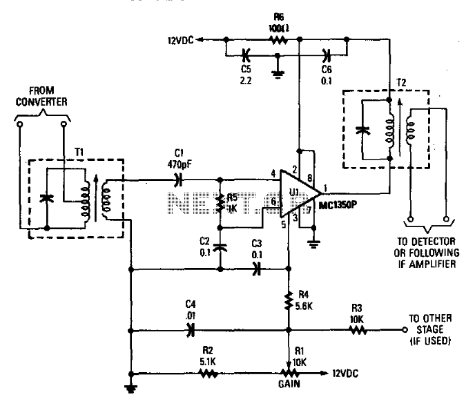
Tl is tuned to the converter output frequency Ul to provide a gain of 45 to 50 dB, depending on the design of Tl and T2. C2, C3, C4, C5, and C6 function as bypass capacitors. R5 serves as...
The circuit was designed to obtain signals through amplitude modulation, exhibiting good sensitivity and selectivity. Amplitude modulation. The amplitude modulation (AM) circuit is engineered to effectively capture and process radio frequency signals. The design focuses on achieving high sensitivity, allowing...
A schematic diagram of the remote-control receiver is presented. The core component of the circuit is IC1, a PIC16C54 8-bit CMOS microcontroller produced by Microchip. The microcontroller retains its data in IC2, a 93LC46 1-kbit serial EEPROM (electrically erasable...
The selection is made with ceramic filters. This 27 MHz receiver operates with an intermediate frequency of 455 kHz. The circuit employs ceramic filters for signal selection, which are known for their high selectivity and low insertion loss. Ceramic filters...
An IR remote control is a widely used device found with televisions, VCRs, and home theaters. It can also be utilized to control personal devices such as lights and air conditioning. Remote controls operate using infrared (IR) light, which...