
DC Drill Speed Controller Circuit

This circuit utilizes a pulse-width modulation (PWM) technique to control the speed of a DC motor, which is commonly found in mini-drill machines. The primary components of the circuit include a microcontroller or a dedicated PWM controller, a power transistor or MOSFET, a diode for back EMF protection, and a potentiometer for speed adjustment.
The microcontroller generates a PWM signal that varies the duty cycle, effectively controlling the average voltage supplied to the motor. The transistor or MOSFET acts as a switch, turning the motor on and off rapidly based on the PWM signal. The diode is connected in parallel with the motor to protect the circuit from voltage spikes generated when the motor is switched off, a phenomenon known as back electromotive force (back EMF).
The potentiometer allows the user to set the desired speed by varying the resistance in the circuit, which in turn adjusts the PWM signal's duty cycle. This setup provides a smooth and efficient way to control the speed of the drill, enhancing the versatility and usability of the mini-drill machine for various applications.
When designing this circuit, considerations should be made regarding the power ratings of the components to ensure they can handle the operational current and voltage. Additionally, proper heat dissipation methods should be implemented for the transistor or MOSFET to prevent overheating during prolonged use.With the help of this DC drill speed controller circuit you can control the number of revolutions of your drilling machine. A mini-drill machine is always.. 🔗 External reference
Related Circuits
A buzzer circuit utilizes a PIC microcontroller to drive a piezo buzzer. The microcontroller is a low-power processor that is ideal for portable and compact devices where battery conservation is essential. The buzzer circuit employs a PIC microcontroller, which serves...
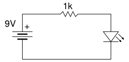
Beginner's Tutorial 1: Building a Circuit on Breadboard - how to build a simple and easy circuit on a breadboard for beginners in electronics. Learn to use an LED and a resistor. This tutorial serves as an introductory guide for...
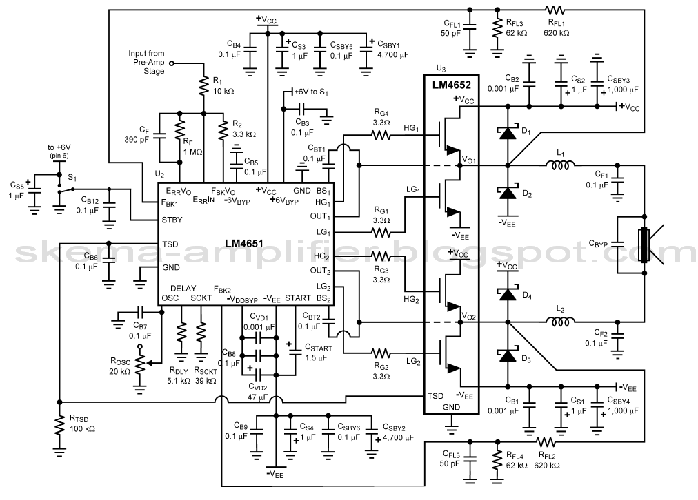
The LA4440 is a two-channel audio power amplifier integrated circuit (IC) designed for stereo and bridge amplifier applications. In dual mode, it provides an output of 6 watts per channel, while in bridge mode, it can deliver up to...

Ethernet is the most widely used networking technology, known for its high reliability, informative media, and ease of expansion and updates. It is commonly utilized in businesses, schools, and various other fields. According to the IEEE802.3 Ethernet specification, the...
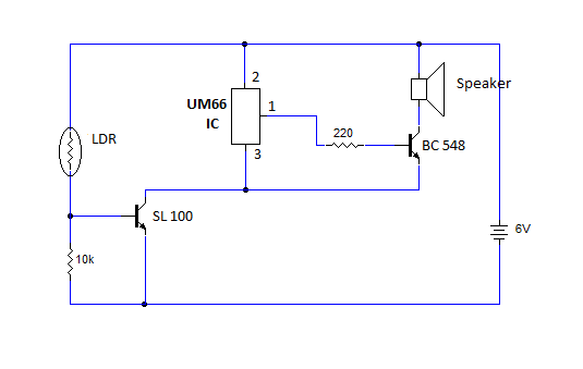
This article provides instructions for creating a light-sensitive morning alarm circuit. The circuit utilizes an LDR (Light Dependent Resistor) or photoresistor to detect morning light, which triggers the alarm section. When light is detected, the circuit produces a melodious...

This is a simple water level alarm circuit made using a 555 timer IC. The circuit will produce an alarm when the water level reaches a preset level. The water level alarm circuit utilizing a 555 timer IC is designed...