
buzzer circuit pic microcontroller

The buzzer circuit employs a PIC microcontroller, which serves as the control unit for activating the piezo buzzer. The piezo buzzer itself is a transducer that converts electrical energy into sound, making it suitable for auditory alerts and notifications in various applications. The choice of a PIC microcontroller is noteworthy as it provides precise control over the buzzer's operation while maintaining low power consumption, which is crucial for battery-operated devices.
In designing the circuit, the microcontroller's output pin is connected to the piezo buzzer. A simple switching mechanism can be implemented using a transistor if higher current is required by the buzzer than the microcontroller can provide directly. Additionally, resistors may be included to limit current and protect the microcontroller from potential damage.
The programming of the microcontroller can be accomplished using an integrated development environment (IDE) compatible with PIC devices. The firmware can be designed to generate different frequencies and duty cycles, allowing the buzzer to produce various tones or patterns, which can be useful for signaling different conditions or alerts.
Overall, this combination of a PIC microcontroller and a piezo buzzer creates an efficient and effective solution for sound generation in compact electronic devices, ensuring that users receive timely auditory feedback while optimizing battery life.buzzer circuit, pic microcontroller, piezo buzzer is a computer chip. It is overkill for driving a piezo buzzer. It is certainly a very low power processor that is optimum for portable and small devices where battery power must be conserved.. 🔗 External reference
Related Circuits
Each zone uses a normally closed contact. These can be micro switches or standard alarm contacts (usually reed switches). Zone 1 is a timed zone which must be used as the entry and exit point of the building. Zones...
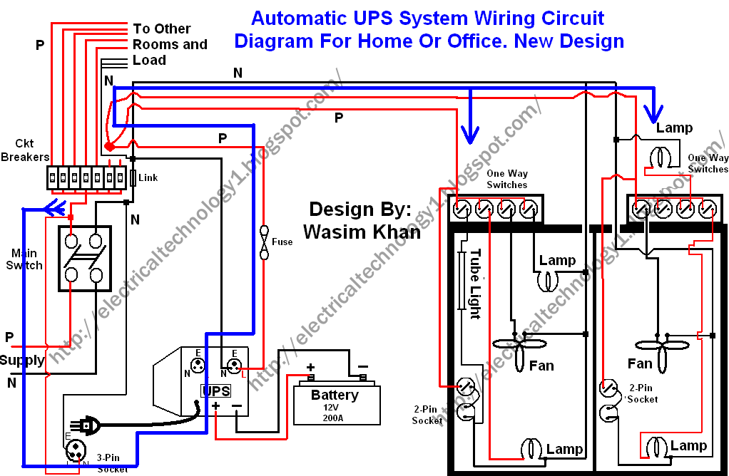
This wiring circuit diagram is designed for providing power to specific rooms in a home or office during a power supply failure. It ensures continuous power supply to devices such as laptops and computers in those particular rooms, especially...
This microphone circuit was submitted by Lazar Pancic from Yugoslavia. The sound card for a PC typically features a microphone input, speaker output, and occasionally line inputs and outputs. The microphone input is designed specifically for dynamic microphones with...

This circuit is designed for a UHF TV antenna and provides a 15 dB preamplification. It is constructed using a transistor and minimal components. The schematic features the BF180 UHF transistor. The first stage consists of a band-pass filter...
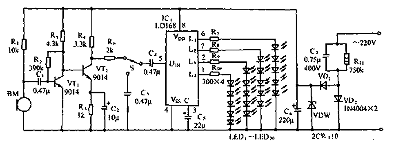
The circuit depicted in the figure involves the LD168, which functions as a sound level indicator for tape recorder speakers. It features four outputs capable of directly driving multiple light-emitting diodes. Additionally, the device can be activated by a...
This circuit is used to power an LED with a voltage of 230V. The 230V must be reduced to meet the LED's voltage requirements. To achieve this, a circuit is necessary as described below. The circuit designed to power an...