
DC Motor-Driver H-Bridge Circuit

The H-bridge circuit is a crucial component in motor control applications, allowing for bidirectional control of DC motors. It consists of four switches, typically implemented using transistors or MOSFETs, arranged in an 'H' configuration. The two vertical legs of the 'H' are connected to the power supply and the motor, while the horizontal legs are the switches that control the flow of current through the motor.
To drive the motor in one direction, two switches are closed (turned on) while the other two switches are open (turned off). This allows current to flow through the motor in one direction. Reversing the motor's direction is achieved by turning off the first pair of switches and turning on the other pair, which reverses the current flow through the motor.
The speed of the motor can be controlled through Pulse Width Modulation (PWM) techniques. By rapidly switching the power to the motor on and off, the average voltage and current supplied to the motor can be adjusted, thus controlling its speed. The H-bridge can also be designed to handle various power ratings depending on the application, making it versatile for use in robotics, automotive systems, and other applications requiring motor control.
In addition to the basic H-bridge configuration, various protection features can be integrated into the design, such as flyback diodes to prevent back EMF from damaging the switches, current sensing to monitor motor load, and thermal protection to prevent overheating. These enhancements ensure reliable operation and longevity of the circuit in demanding environments.
Overall, the H-bridge circuit is an essential building block for effective DC motor control, providing flexibility in operation and ease of integration into larger systems.A very popular circuit for driving DC motors (ordinary or gearhead) is called an H-bridge. It`s called that because it looks like the capital letter `H` on classic schematics. The great ability of an H-bridge circuit is that the motor can be driven forward or backward at any speed, optionally using a completely independent power source. 🔗 External reference
Related Circuits
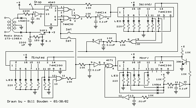
The clock circuit above uses seven ICs and 19 LEDs to indicate binary coded decimal time. The LEDs can be arranged so that each horizontal group of 3 or 4 LEDs represents a decimal digit between 0 and 9...
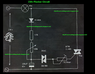
This circuit operates at 230V and can be utilized for party decoration purposes. It is sourced from an old circuit book titled "100 Circuit Book." The components include DIAC ER 900 and TRIAC BTW 11-400. The circuit is designed to...
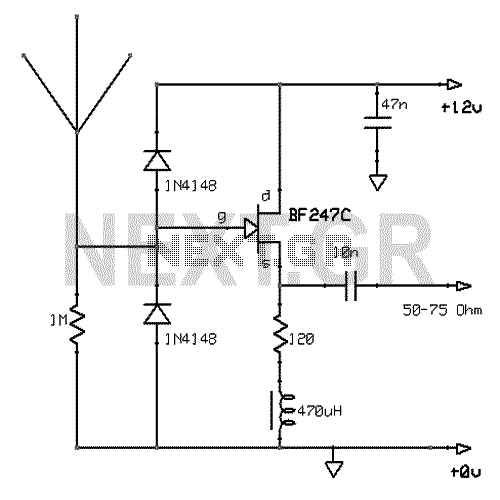
This active antenna schematic can be used to frequency range from 10 KHz to 100 MHz. The length of the Antenna can be between 0.5 to 1 meter long. The power consumption is 20-30mA. More: Use the shortest possible...
The circuit presented is a digital fan regulator that offers five speed levels, similar to conventional fan regulators. This ceiling fan controller utilizes readily available components. An optional 7-segment display with associated circuitry is included to show the selected...
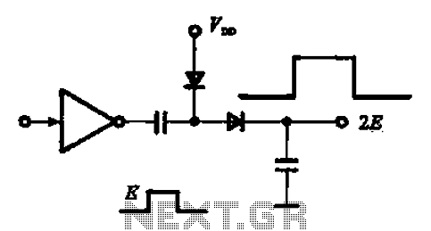
A pulse booster circuit is utilized to increase the pulse amplitude. The structure illustrated in figure (a) of the circuit can output a pulse amplitude that is twice that of the input. Figure (b) of the circuit can achieve...
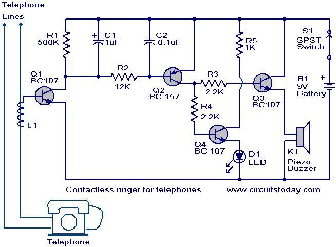
The contactless telephone ringer circuit is designed to produce an audible ring and a visual indication when a call is received. Its primary advantage lies in the absence of direct contact between the telephone line and the circuit, which...