
A pulse booster circuit

The pulse booster circuit is designed to enhance the amplitude of input pulses, making it suitable for applications where signal strength is critical. The circuit typically employs a combination of transistors, capacitors, and resistors to achieve the desired amplification. In figure (a), the circuit configuration is likely to include a transistor configured as a common emitter amplifier, where the input pulse is fed into the base terminal. The collector terminal outputs a pulse that is amplified, resulting in an output that is double the amplitude of the input pulse.
In figure (b), the circuit is configured to amplify negative pulses. This may involve using a complementary push-pull arrangement of transistors to ensure that both positive and negative portions of the input waveform are effectively amplified. The design may also include feedback mechanisms to stabilize the output and prevent distortion, ensuring that the pulse shape is maintained while increasing amplitude.
The choice of components such as the type of transistors (e.g., NPN or PNP), the values of resistors and capacitors, and the power supply voltage will significantly influence the performance of the pulse booster circuit. Proper selection and configuration of these components are essential for achieving the desired amplification while maintaining signal integrity. Additionally, considerations regarding bandwidth, rise and fall times, and thermal management should be taken into account when designing and implementing a pulse booster circuit for specific applications.A pulse booster circuit When you need to increase the pulse amplitude, pulse boost circuit can be used, its structure, the figure (a) of the circuit can output pulse amplitude is twice the amplitude of the input, figure (b) of the circuit can be obtain twice the amplitude of the negative pulse.
Related Circuits
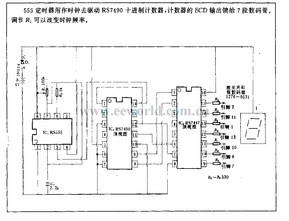
The 555 timer is utilized as a clock source to drive the RS7490 decimal counter, providing a BCD output to a 7-segment LED display. The clock frequency can be adjusted by changing the value of resistor R1. The circuit operates...
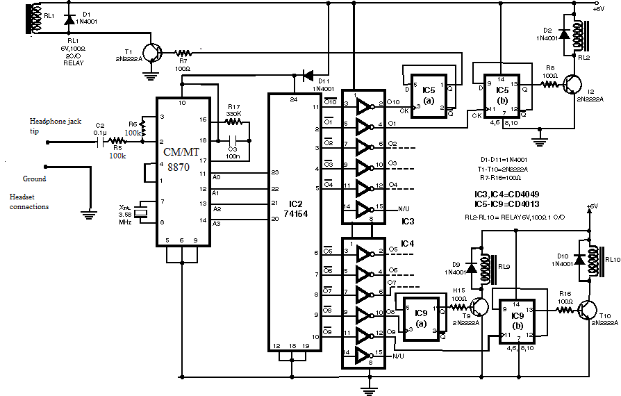
Have you ever imagined controlling your home appliances using your cell phone? Numerous circuits exist for this application, typically utilizing a telephone. This circuit has been modified and redesigned for compatibility with a standard cell phone headphone jack. To...
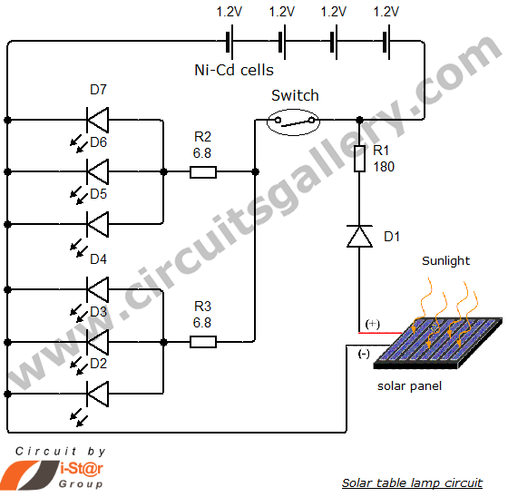
Solar energy has become a popular alternative for electricity production. This project focuses on teaching school students how to create solar lamps for their homes. The primary components of this simple solar lamp circuit include a small solar panel...

This circuit is for an audio equalizer that is commonly found in commercial products such as high-fidelity systems, car audio, and stage equipment; however, published circuits for these devices are quite rare. This design features equalizer bands. The circuit...
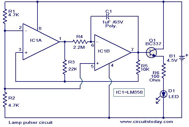
This circuit is designed to gradually pulse an LED or a low-power filament lamp, creating a visual effect where the light transitions from an OFF state to full brightness and then back down to OFF. Such a circuit is...
Connect a 12V fan to this circuit that consumes 70mA (0.07A), ensuring the circuit can supply at least that amount of current. There appears to be a misunderstanding regarding the analysis. The voltage drop across the resistor equals the...