
DC motor PWM speed control

The 555 provides good current capability to drive the MOSFET fast and to drive a bipolar transistor. This system can be utilized to drive the DC motor of a small rotary spark gap Tesla coil at variable speed. If the 1KHz hum of the motor is undesirable, it is possible to increase the frequency beyond the audible range by replacing the potentiometer. However, it should be noted that at higher frequencies, the inductive reactance of the motor increases, which can lead to a decrease in efficiency.
It is crucial that the MOSFET or bipolar transistor has sufficient current capability to drive the motor, with the drain or collector current needing to equal the maximum motor current at the power supply voltage when it is blocked. Additionally, the snubber diode must be capable of handling the current, as it shorts the motor during the off cycle. Both the MOSFET (or bipolar transistor) and the diode should be connected to a heatsink if the maximum motor current exceeds 100 or 200 mA to prevent overheating of the components.
For applications where braking during the off cycle is not desired, a resistor can be placed in series with the snubber diode. This configuration may improve efficiency but will result in increased inertia when slowing down the motor. The resistor value can be calculated using the formula R = V(breakdown transistor) / Imax, and the power rating of the resistor should be at least 5W to ensure reliable operation.The 555 Ic is wired as an astable and the frequency is constant and independent of the duty cycle, as the total resistance (R charge + R discharge, notice the diode) is constant and equal to 22Kohm (givin a frequency of about 1Khz, notice the hum). When the potentiomenter is all up, the Rcharge resistance is 1,0 Kohm (the diode prevents the capacitor to charge through the second potentiometer section and the other 1,0 Kohm resistor) , and Rdischarge is 21 Kohm, giving a 5% on duty cycle and a 1Khz frequency.
When the potentiomenter is all down, the Rcharge resistance is 21,0 Kohm (the diode prevents the capacitor to charge through the second potentiometer section and the other 1,0 Kohm resistor) , and Rdischarge is 1 Kohm, giving a 95% on duty cycle and a 1Khz frequency. When the potentiomenter is at 50% , the Rcharge resistance is 11,0 Kohm (the diode prevents the capacitor to charge through the second potentiometer section and the other 1,0 Kohm resistor) , and Rdischarge is 11 Kohm, giving a 50% on duty cycle and a 1Khz frequency. The 555 provide good current capability to drive the mosfet fast and to drive a bipolar transistor. I actually use this system to drive the DC motor of my small Rotary spark gap Tesla coil at variable speed If you are disgusted by the 1Khz hum of the motor try to rise the frequency out of the audible range (replacing the potenziometer), but rembember that at higher frequency inductive reactance of motor rises so the the efficiency would drop.
Important: Obviously the mosfet (or bipolar) must have enough current capability to drive the motor, so the drain (or collector) current must be equal to maximum motor current (at power supply voltage, when it is blocked). The snubber diode too, because it shorts the motor on the off cycle. Both mosfet (or bipolar) and diode have to be hooked (if you don't want them cooked ;-) ) to a heatsink if the max motor current is more than 100 or 200mA.
I suggest to not stress to much the motor with too much work because it overheats both motor, transistor and diode. If you don't want braking in the off cycle just place a resistor in series with the snubber diode, it should rise a bit efficiency but have more inertia when slowing the motor down.
The value of the resistor must be R=V(breakdown transistor) / Imax, and the power should be 5W. 🔗 External reference
Related Circuits
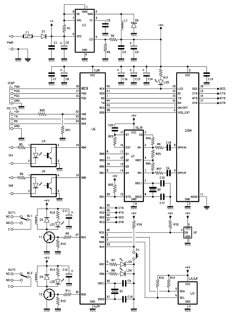
The entire remote control is managed by a PIC that oversees the GSM/GPRS module's operations, monitors room temperature via a Dallas DS1820 smart probe, controls the logical state of two opto-isolated inputs, and sends commands to two relays. Additionally,...
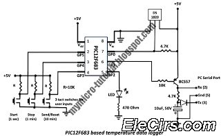
A data logger is a device that records measurements over time. The measurements could be any physical variable like temperature, pressure, voltage, humidity, etc. This project describes how to build a mini logger that records surrounding temperature. A data logger...
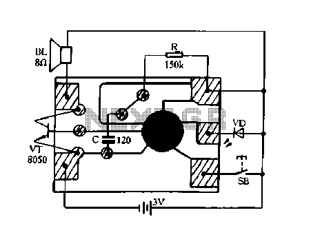
Constantly changing light and sound analog controller circuit 02 The circuit described is an analog controller designed to modulate light and sound in a dynamic manner. It typically utilizes components such as operational amplifiers, resistors, capacitors, and transistors to achieve...
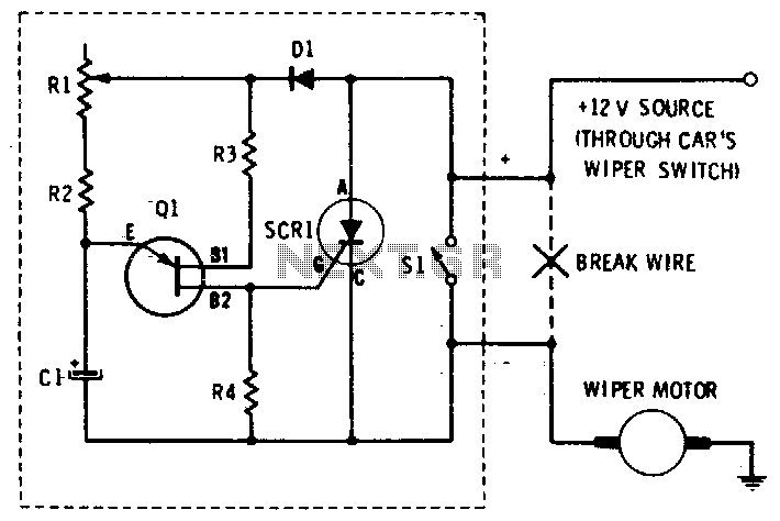
This circuit provides complete speed control over a car's windshield wipers. The wipers can be slowed down to any rate, even down to four sweeps per minute. The controller consists of two principal circuits: the rate-determining circuit, which is...
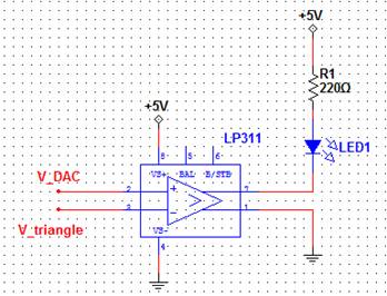
A pulse-width modulated (PWM) signal can be generated using a triangle wave and a comparator. The digital-to-analog converter (DAC) serves as the input signal, and the resulting output signal's duty cycle will be proportional to the input voltage. This...
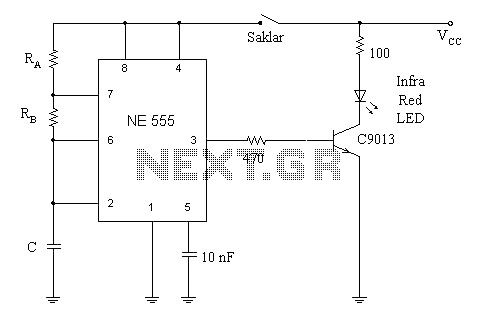
A simple circuit diagram illustrates a schematic for a remote control system, which consists of two components: a transmitter and a receiver. The transmitter circuit is controlled by the NE555 integrated circuit (IC). This system operates by detecting the...