
remote control using the ne 555 and lm 567

The remote control system consists of a transmitter and a receiver, each designed to operate on specific frequencies. The transmitter employs the NE555 timer IC, which is configured in astable mode to generate a square wave signal at a desired frequency. Alternatively, the LM567 can be used as a frequency generator to achieve similar results. The frequency output of the transmitter must be precisely matched to the frequency input of the receiver to ensure effective communication.
In the receiver circuit, the LM567 is utilized as a tone decoder, which is sensitive to the frequency generated by the transmitter. The variable resistor R1 allows for fine-tuning of the receiver's sensitivity to the incoming signal. By adjusting R1, the user can optimize the receiver's ability to detect the transmitter's signal, which is verified by the activation of a relay. This relay serves as an output mechanism, indicating successful reception of the signal.
The design of the remote control system includes multiple channels, each operating at different frequencies to prevent interference. It is essential to maintain a frequency separation of at least 5 kHz between channels to ensure that the LM567 can effectively distinguish between them. This careful consideration of frequency management allows for reliable operation of the remote control system in various applications, such as controlling electronic devices or systems wirelessly. The overall schematic design should be carefully laid out to facilitate easy assembly and troubleshooting, ensuring that all components are correctly connected and that the circuit functions as intended.Simple circuit diagram is a schematic remote control, remote control where it consists of two parts of the transmitter and receiver. The first part is a transmitter, circuit diagrams for transmitter IC is controlled by the NE555. This system works by detecting the signal emitted frequency. Frequency signal so that the transmitter circuit (NE 555, can also use the LM 567 as a generator frequency) must be equal to the frequency decoder. The following is a schematic remote control drawing transmitter: To facilitate the process of tunning, the R1 is a resistor in the receiver variable. While the transmitter is a fixed value. When the circuit is ready, so the system works well, the first step taken is to tunning, by way of the transmitter is turned on continuously, while the receiver R1 to set the value to be able to detect the signal transmitter (can be determined by the reaction of the relay is clicked).
For the second part is a circuit diagram of the receiver, the receiver is controlled by the LM567. The following is a schematic remote control drawing receiver: In the picture on top of each channel is designed with a different frequency. By considering the bandwidth of the frequency detection signal LM 567, inter-frequency channels should have a big enough difference, let`s try remote control with a difference of 5 KHz.
🔗 External reference
Related Circuits
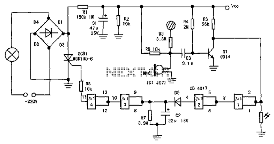
The circuit diagram illustrates a sound, light, and touch-controlled delay self-extinguishing switch. It comprises three main sections: the power circuit, the signal conversion detecting circuit, a delay circuit, and a control circuit. 1. Power Circuit: This section consists of...

The circuit is designed to regulate a dual power supply that provides +12V and -12V from the AC mains. Such a power supply is an essential tool for an electronic hobbyist's workbench. The schematic of the circuit includes components...
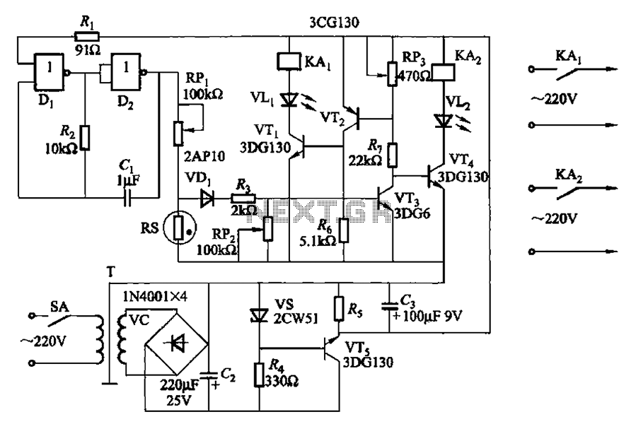
Two NAND gates (Di, Dz) and a resistor (Rz) along with capacitors (C1, etc.) form an RC self-excited multivibrator with an oscillation frequency of 2.5 Hz and an oscillation amplitude of 4 V. This circuit is used as a...
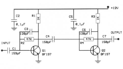
The following circuit illustrates a 20 dB VHF amplifier circuit diagram utilizing the BF197 transistor. Features include a simple circuit design. The 20 dB VHF amplifier circuit is designed to amplify very high frequency signals, making it suitable for applications...
Automated frog call data loggers have been effectively utilized to gather information on: (1) species presence during sampling, enabling the reliable recording of species that may be overlooked due to time constraints; (2) life history and phenology details, such...
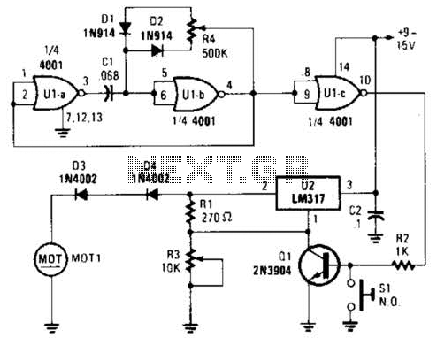
Connected in this manner, an LM317 1-A adjustable-voltage regulator can be utilized to control the speed of a miniature DC motor or to adjust the brightness of a small lamp. The circuit achieves this by modulating the pulse width,...