
DC Motors and Stepper Motors used as Actuators

DC motors, electrical motors, and stepper motors are integral components in various applications, functioning as actuators to convert electrical energy into mechanical motion. Each type of motor operates on distinct principles and is suited for different tasks.
DC motors are characterized by their simplicity and efficiency in converting direct current electrical energy into rotational motion. They typically consist of a rotor, stator, commutator, and brushes. The rotor, or armature, is the rotating part of the motor, while the stator provides a magnetic field. The direction and speed of the motor can be controlled by varying the voltage supplied to it. Pulse Width Modulation (PWM) is a common technique used to efficiently control the speed of DC motors by adjusting the average voltage delivered to the motor, thereby managing its power consumption and performance.
Electrical motors encompass a broader category that includes AC motors, which differ from DC motors in that they operate on alternating current. These motors can be further classified into synchronous and asynchronous types, each with unique characteristics suitable for specific applications. Synchronous motors maintain a constant speed regardless of the load, while asynchronous motors, or induction motors, vary their speed based on the load conditions.
Stepper motors are a specific type of electric motor that move in discrete steps, allowing for precise control of position and speed. They are widely used in applications requiring accurate positioning, such as 3D printers, CNC machines, and robotics. The control of stepper motors is typically achieved through a sequence of electrical pulses, which energize the motor coils in a specific order to produce movement.
Transistor H-bridge motor control is a technique utilized to control the direction and speed of DC motors and stepper motors. An H-bridge circuit consists of four switches (transistors) arranged in an "H" configuration, allowing current to flow through the motor in either direction. By turning on different combinations of the transistors, the H-bridge can reverse the motor's direction or stop it entirely. This method provides a flexible and efficient means of motor control, enabling complex motion patterns and precise speed regulation.
In summary, understanding the principles and control methods of DC motors, electrical motors, and stepper motors is crucial for designing effective actuator systems in various electronic applications. The integration of PWM and transistor H-bridge control enhances the functionality and efficiency of these motors, making them essential components in modern electronic devices.Electronics Tutorial about DC Motors, Electrical Motors and Stepper Motors used as Actuators including PWM and Transistor H-bridge Motor Control.. 🔗 External reference
Related Circuits
This integrated circuit is highly efficient and does not require any external glue logic for operation. It features two pins to control a motor: one for direction and the other for stepping pulse triggers. The design is compact and...
A footstepping effort-based locomotion interface is described. Built around an inexpensive and readily available exercise machine, it provides an effective interface for walking through virtual environments. The footstepping effort-based locomotion interface utilizes a low-cost exercise machine, such as a treadmill or...
The following circuit illustrates a stepper motor controller based on the PIC16F84A integrated circuit. It features a transistor used for driving the motor. The stepper motor controller circuit utilizes the PIC16F84A microcontroller, which is a popular choice for controlling stepper...
Stepper motors are a frequently discussed topic. This circuit converts a clock signal from a square wave generator into signals that have a 90-degree phase difference, which are necessary for driving the stepper motor windings. The trade-off for this...
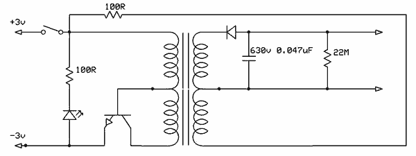
Free energy motors and generators are available for purchase, featuring plans for overunity devices. These devices resemble oscillators used in Joule thief circuits, although there may be some errors present in the designs. However, the concept remains clear. Free energy...
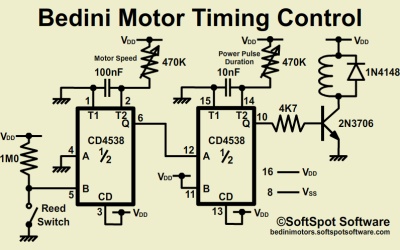
It is important to note that the Bedini Trifilar SG or SSG are not over-unity (OU) systems. They function as one-to-one energy shuttle systems, utilizing one charged input battery to recharge four or more output batteries. When configured correctly,...