
Stepper motor controller Based On The PIC16F84A IC

The stepper motor controller circuit utilizes the PIC16F84A microcontroller, which is a popular choice for controlling stepper motors due to its versatility and ease of programming. The microcontroller is responsible for generating the control signals required to drive the stepper motor in a precise manner.
In this configuration, the circuit typically includes a series of transistors that act as switches, allowing the microcontroller to control the power supplied to the motor coils. The transistors are connected to the output pins of the PIC16F84A, which sends PWM (Pulse Width Modulation) signals or logic high signals to turn the transistors on and off. This switching action enables the motor to step in discrete increments, allowing for accurate positioning and control.
The circuit may also include additional components such as resistors, capacitors, and diodes to protect the transistors from back EMF generated by the motor coils and to filter the signals. A power supply is essential to provide the necessary voltage and current for the stepper motor operation.
To ensure proper functionality, the microcontroller is programmed with a specific algorithm that dictates the sequence in which the transistors are activated. This sequence is crucial for determining the direction of the motor's rotation and the speed at which it operates. By adjusting the timing of the signals sent to the transistors, the motor can be controlled effectively for various applications, including robotics, CNC machines, and automation systems.
In summary, this stepper motor controller circuit demonstrates a practical application of the PIC16F84A microcontroller, showcasing its ability to manage motor control through a well-structured design and programming approach.The following circuit shows about Stepper motor controller. This circuit based on the PIC16F84A IC. Features: transistor is used to drive the . 🔗 External reference
Related Circuits
A closed-loop or servo system has the capability to stabilize the controlled plant at a specified operating condition. The plant, which is the controlled sub-system, can be... A closed-loop control system, commonly referred to as a servo system, is designed...
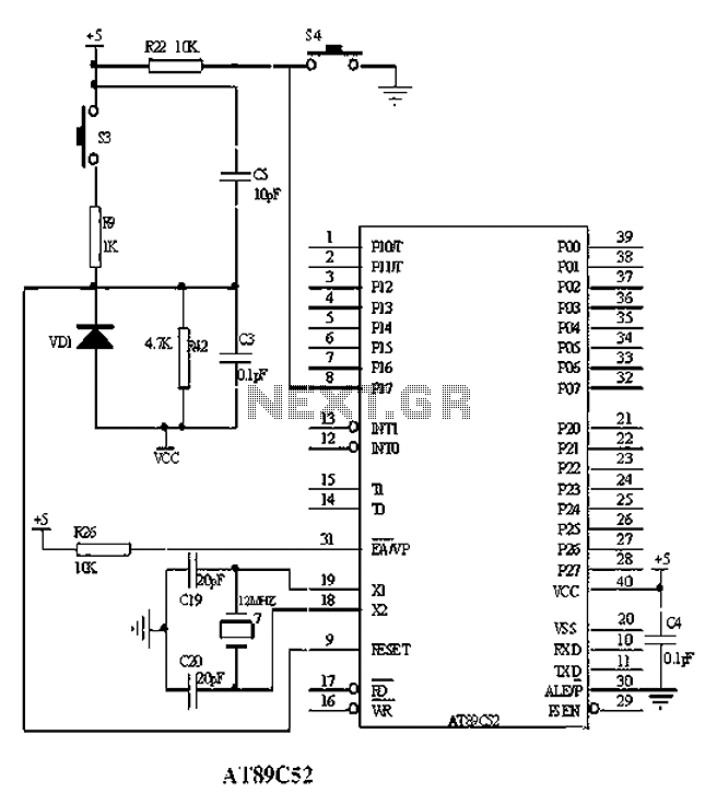
The American Atmel AT89C52 is a low-voltage, high-performance CMOS 8-bit microcontroller chip that contains 8KB of rewritable program memory and 256B of random access data memory (RAM). Atmel's high-density devices utilize non-volatile memory technology and are compatible with the...
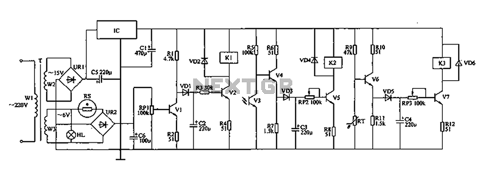
The automatic controller for a chicken coop is designed to automatically regulate light, temperature, and humidity, thereby enhancing egg production and survival rates of chickens. This device is intended for specialized poultry households in rural areas. The circuit operates...
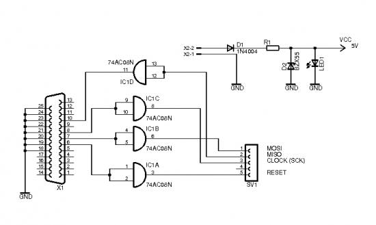
This ISP Programmer can be utilized for in-system programming or as a standalone SPI programmer for Atmel ISP programmable devices. The programming interface is compatible with STK200 ISP programmer hardware, allowing users of STK200 to also use the software...
The brain of the robot is composed of an Atmel Tiny2313 microcontroller. This MCU features In-System Programming, allowing programming of its memory using a low-cost programmer. A simple programmer connects to the parallel port and is described in the...
Electronics tutorial about DC motors, electrical motors, and stepper motors used as actuators, including PWM and transistor H-bridge motor control. DC motors, electrical motors, and stepper motors are integral components in various applications, functioning as actuators to convert electrical energy...