
DC-RRS Application Circuit b

The DC solid-state relay (DC-SSR) serves as a crucial component in controlling high-power loads in various applications, such as industrial automation, heating systems, and motor control. The primary function of the DC-SSR is to switch high currents and voltages without mechanical contacts, thereby improving reliability and longevity.
In the schematic, the DC-SSR is connected in series with the high-power load, which may consist of resistive, inductive, or capacitive components. The input control circuit typically includes a low-power control signal, which can be generated by a microcontroller or a manual switch. This control signal activates the DC-SSR, allowing current to flow through the load circuit.
The DC-SSR features an opto-isolation mechanism that provides electrical isolation between the control side and the load side, ensuring that any high voltage or current fluctuations on the load do not affect the control circuitry. The relay's output characteristics depend on the specific model, with ratings typically ranging from a few amps to several hundred amps, suitable for various high-power applications.
Additionally, the high-power load driving circuit (shown in diagram b) may incorporate protective components such as fuses or circuit breakers to safeguard against overcurrent conditions. It may also include snubber circuits to mitigate voltage spikes caused by inductive loads, enhancing overall circuit stability.
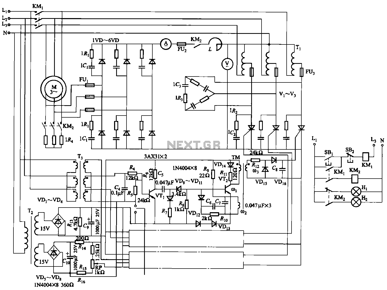
In summary, the combination of a DC-SSR and a well-designed high-power load driving circuit allows for efficient and safe control of high-power devices, making it an essential configuration in modern electronic systems.DC solid state relay (DC-SSR) driving high-power load circuit is shown in (a) below; high power load driving circuit shown in (b) below.
Related Circuits
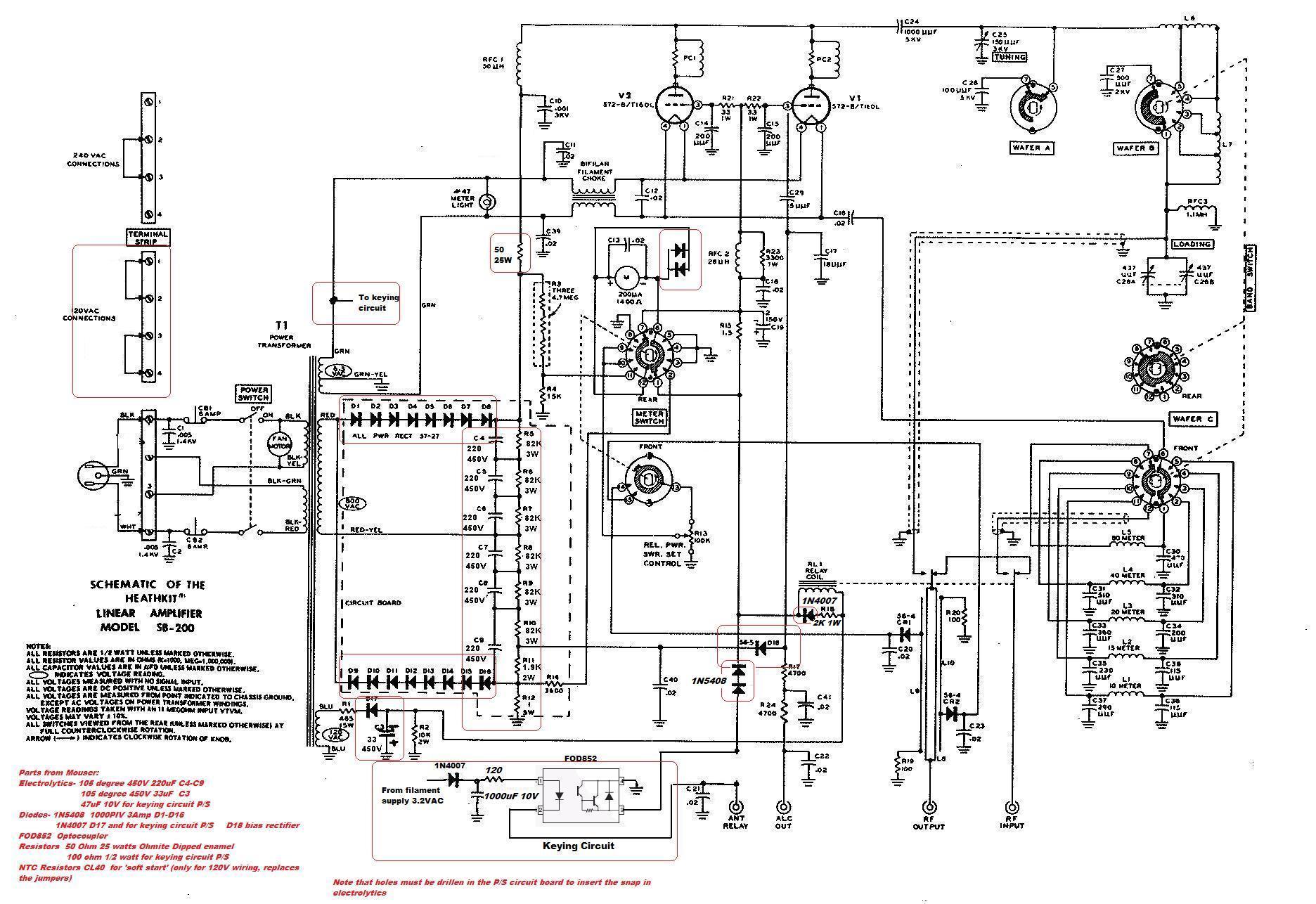
This circuit serves as a cost-effective alternative to commercially available keying circuits. It has been successfully implemented in the SB-200 amplifier. A schematic of the modified SB-200 is provided. The described circuit is designed to function as a keying mechanism...

The circuit described is a crystal oscillation circuit using a CM OS inverting configuration, designed to ensure accurate operation. It employs a BCD counter (IC2) capable of achieving a maximum oscillation frequency of 2 MHz, which is 100 times...
This Intercom is powered by two 9-volt batteries and uses only current when the Intercom is used. Both units are connected via a two-wire little cable or simply two wires (dotted lines). The loudspeakers act both as loudspeakers and...
This schematic illustrates a beeper circuit designed to produce a continuous beep sound while simultaneously flashing an LED. The beeper circuit typically consists of a few key components: a sound-generating device (such as a piezo buzzer), an LED for visual...
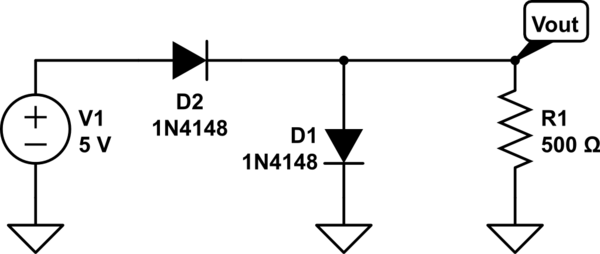
The two diodes will fail. It is advisable to include series resistors for them. If the simulation is successful, the current through the diodes will be excessive. Both diodes do not necessarily need to fail; one may become a...
The circuit depicted in Figure 3-170 illustrates a wound rotor induction motor operating at various speeds, with a voltage (turn difference frequency EMF) U induced in the rotor. The rotor open circuit voltage is represented as Uo (Us0). A...