
tda2005 car audio amplifier circuit diagram project

The TDA2005 car audio amplifier circuit is a versatile solution for automotive audio applications, providing high-quality sound amplification with efficient power management. The device's bridge mode configuration is particularly advantageous for applications requiring higher power output while maintaining low distortion levels. The integration of short circuit and thermal protection mechanisms enhances reliability, making the amplifier suitable for various automotive environments where conditions may vary significantly.
In terms of circuit design, the TDA2005 can be easily integrated into existing audio systems due to its low component count and straightforward implementation. The Multiwatt 11 package allows for efficient thermal dissipation, crucial for maintaining performance during prolonged use. The amplifier's capability to operate within a wide voltage range ensures compatibility with various power supply configurations found in automotive applications.
Overall, the TDA2005 amplifier is an excellent choice for enhancing audio performance in vehicles, offering flexibility in configuration and robust protection features, making it suitable for both novice and experienced designers in the field of automotive electronics.This TDA2005 car audio amplifier circuit is specially designed to work on devices like : car radios, cd-players and similar devices. This car radio audio amplifier circuit is based on the TDA2005 audio IC which can provide a maximum output power of 20 watts into a 4 ohms load, connected in bridge mode configuration.
The TDA2005 audio IC is a c lass B audio amplifier designed in a Multiwatt 11 package and can be ordered in two types TDA2005M used for bridge mode application or TDA2005S used in stereo applications. If the TDA2005 is used in stereo mode it can deliver a 10 + 10 watts output power in a 2 ohms load. The advantage of using the TDA2005 audio amplifier in bridge mode configuration is that the total harmonic distortion ( THD) is 1% and the THD for the stereo configuration mode is 10 %.
This audio amplifier IC supports a wide range of input voltage from 8 volts up to 18 volts and it has many features like : short circuit protection, overrating chip temperature, low external components required, bridge or stereo booster amplifiers with or without boostrapand with programmable gain and bandwidth, no electrical isolation between the package and the heatsink. 🔗 External reference
Related Circuits
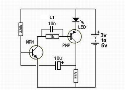
Most blog posts involve short 3-4 hour projects or hacks that are built for learning and enjoyment. It was time to develop something more substantial. The project described appears to focus on creating electronic circuits that can be completed within...
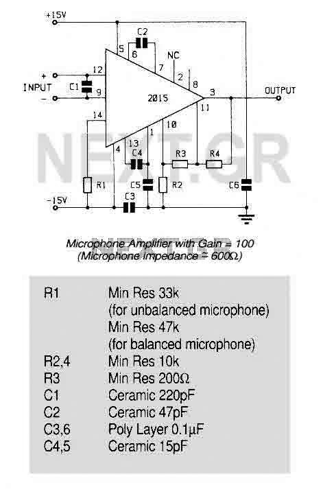
An ultra low noise audio preamplifier particularly suited to microphone preamplification including balanced microphones. The IC features wide bandwidth, low distortion only 0.007% at a gain of 100, and very low noise only 1.3nV/Hz for source impedance up to...
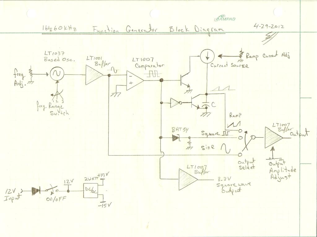
Oscillation is expected at the resonant frequency where the positive feedback is in phase with the input, specifically at 0 degrees. For oscillation to take place, the gain must be equal to or greater than 1 at that frequency....
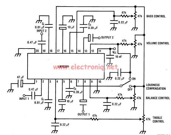
This volume controller equalizer electronic project is designed using the LM1036 DC tone volume controller, featuring a volume and balance circuit for stereo applications. The four control inputs of the LM1036 volume controller enable the control of bass, treble,...
The figures (a) and (b) illustrate AC measuring circuits. Figure 21(a) presents a current measuring schematic diagram utilizing a magnetic balanced mode Hall device. When the magnetic field generated by the measured current, denoted as IN, is B1, this...
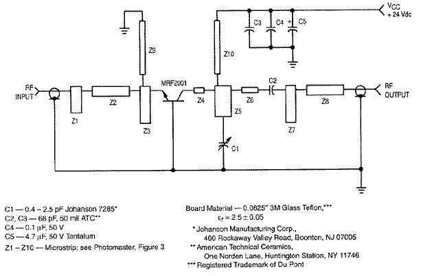
RF amplifier circuit diagram, delivering 1W for 2.3GHz, built based on MRF2001. This RF amplifier provides approximately 1 Watt power output with a minimum gain of 8 dB at a 24V voltage supply. The frequency can be tuned from...