
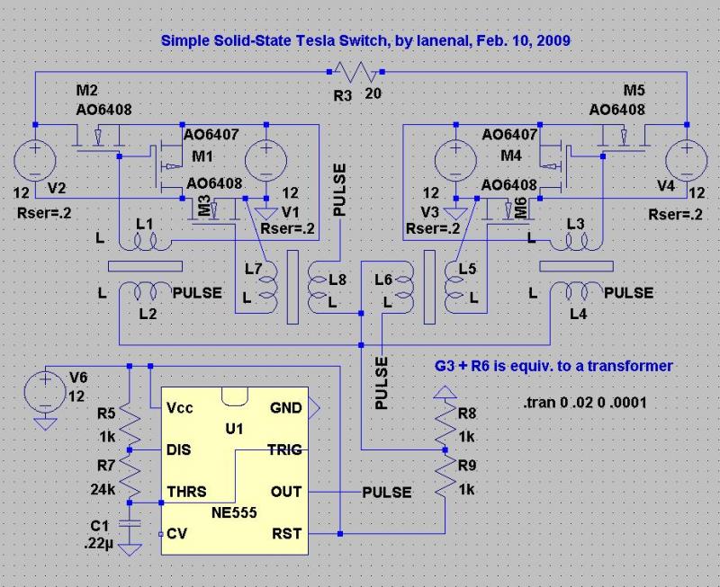
dc tesla coil

The circuit design involves a small DC Tesla coil that utilizes a rotating spark gap for generating high-voltage discharges. The motor responsible for the rotary spark gap operates at a full load current of approximately 3.8 amps, while the 555 timer, which is used for pulse modulation to control the timing of the spark gap operation, draws around 4 amps.
When considering the configuration of the power supply connections, two primary options exist: connecting the motor and the 555 circuit in parallel or in series. Connecting these components in parallel from a +12V supply allows both the motor and the 555 timer to operate independently, ensuring that each component receives the necessary voltage without affecting the other's performance. This configuration is typically preferred for applications where consistent voltage and current are critical for reliable operation.
Conversely, if the motor and the 555 circuit were to be connected in series, the total current flowing through the circuit would be determined by the component with the highest resistance, which could lead to a situation where the 555 timer is subjected to higher currents than it is rated for. This could potentially damage the timer or lead to erratic behavior, as the motor's current draw may exceed the acceptable limits for the control circuit.
The schematic includes dotted lines to indicate the components under consideration, with points A and B clearly illustrating the parallel connection configuration, while point C represents the series connection. The design should prioritize the parallel connection to prevent any issues related to current draw, ensuring that both the motor and the 555 timer function optimally without risk of overcurrent conditions.
In summary, the preferred configuration for this circuit would be to connect the motor and the 555 control circuit in parallel to the +12V supply, thereby safeguarding the integrity of the components and maintaining stable operation of the small DC Tesla coil system.I`m making a small DC tesla coil with a rotating spark gap. The motor controlling the RSG draws about 3. 8 amps of current at full load, and the 555 control circuit and amp draws about 4 amps. Would it be best to run the motor and 555 circuit parallel from the +12v or in series If it`s in series would the motor current draw cause an excess of curr ent through my 555 or am I looking at it wrong Sorry for the non-conventional elements of the schematic. The dotted lines represent the elements of the circuit I`m questioning. A and B are the same thing, obviously. They both represent the motor connected in parallel to the signal circuit, but C (without the ground to the left of it) would be the motor connected in series to the main circuit.
After posting this thread I realized it was probably a stupid question and I should just connect the motor in parallel, but I was wondering: would connecting the motor in series would cause more current to be drawn to the coil 🔗 External reference
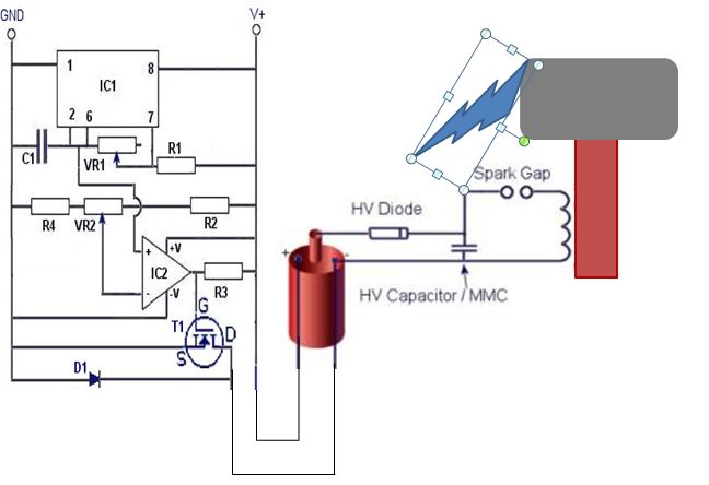
Related Circuits
This circuit is designed for ease of tuning. When the pulse voltage reaches 6V, all transistors operate as open switches, eliminating the risk of battery shorts. The pulse voltage source V5 can be substituted with a 555 astable circuit....
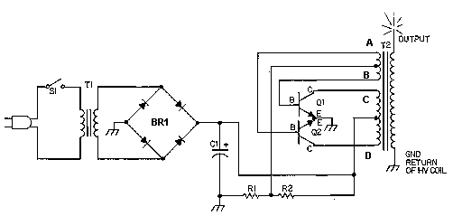
This circuit is designed to demonstrate high frequency and high voltage, capable of producing up to approximately 30 kV, depending on the transformer utilized. It is an economical and straightforward project, primarily using a standard TV flyback transformer. The...

Tesla radiant energy collectors and methods for creating these devices have been explored. Various designs have been developed, including the use of a standard rectification bridge for antenna and ground, a Greinacher voltage quadrupler rectifier, and experimentation with different...
This coil operates from 12V or 24V SLA batteries. A pair of car ignition coils is used to provide approximately 20kV for charging the capacitor bank. The ignition coils are driven by a variable frequency square wave generated by...
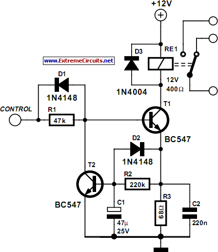
Some relays will become warm if they remain energized for some time. The circuit shown here will actuate the relay as before but then reduce the hold current through the relay coil by about 50%, thus considerably reducing the...
A South African company has developed a 5-kilowatt Fuel Free Generator and discovered that the longevity of the batteries is significantly affected by the process. There are various types of batteries available for testing, including different lead-acid batteries, gel...