
DC to AC inverter H-Bridge

An H-bridge is a circuit configuration that allows for the control of the polarity of a voltage applied to a load, enabling it to drive a motor or other devices in both forward and reverse directions. In this case, the H-bridge will be used to generate an alternating current (AC) output from a direct current (DC) source.
The core components of the circuit include four MOSFETs arranged in an H-bridge configuration. The MOSFETs will be responsible for switching the high-voltage DC to create a square wave output. The 555 timer IC will serve as an astable multivibrator, generating a pulse-width modulation (PWM) signal to control the gates of the MOSFETs. This PWM signal will dictate the timing and duration of the switching, effectively simulating an AC waveform.
To achieve the desired output voltage of 230V AC, the circuit must be designed to handle the high voltage and ensure safe operation. This may involve using appropriate gate driver circuits to ensure the MOSFETs switch efficiently and safely at the required frequency. Additionally, the circuit may require snubber circuits or flyback diodes to protect against voltage spikes caused by the inductive loads.
The output of the H-bridge can be further processed using a transformer to step down the voltage if necessary and to filter the waveform to produce a more sinusoidal output. Careful consideration must also be given to the thermal management of the MOSFETs, as they will dissipate heat during operation, potentially requiring heat sinks or active cooling solutions.
Overall, the design of this H-bridge circuit requires careful attention to component selection, circuit layout, and safety measures to ensure reliable operation in converting 350V DC to 230V AC at 50Hz.Hi everybody. I need H-bridge schematic for 230V 50Hz output from DC 350V, using 555 timer IC and mosfets.. 🔗 External reference
Related Circuits
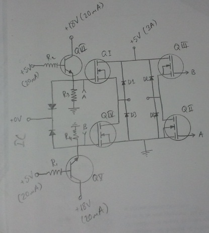
An H-bridge is being utilized with IRF740 MOSFETs to convert 315V DC to 230V AC. However, the upper MOSFETs are frequently damaged within a few seconds, and the cause of this issue has not been identified. The described circuit employs...
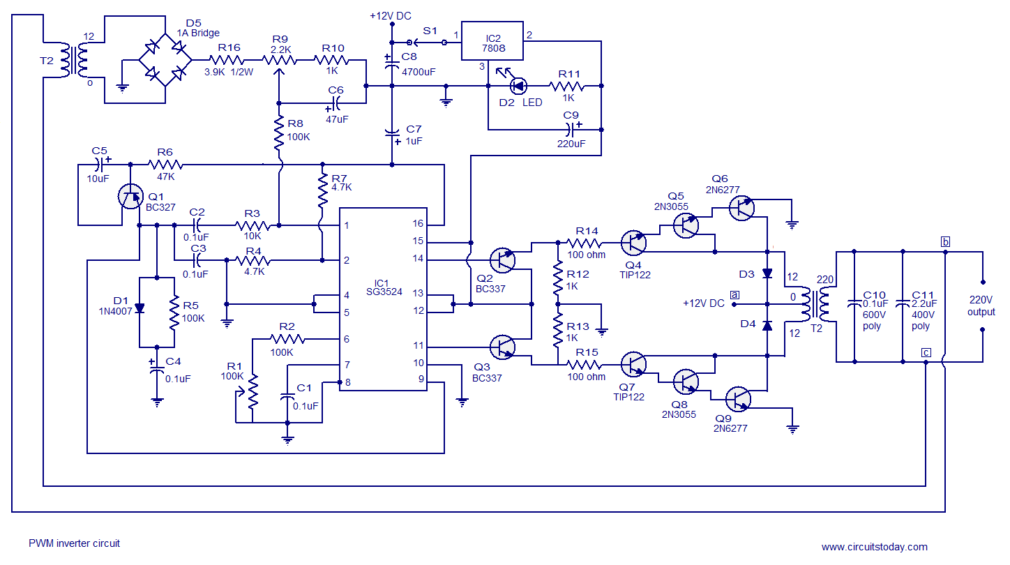
A simple PWM inverter circuit utilizes the SG3524 integrated circuit. This PWM inverter is designed for a 12V input, providing a 220V output with a maximum output power of 250 watts. The output power can be extended further. The described...
This is a simple high-voltage inverter circuit. It uses an NPN transistor type 2N3055. This circuit is designed to invert low voltage to high voltage. The high-voltage inverter circuit utilizing the 2N3055 NPN transistor serves as an effective means to...
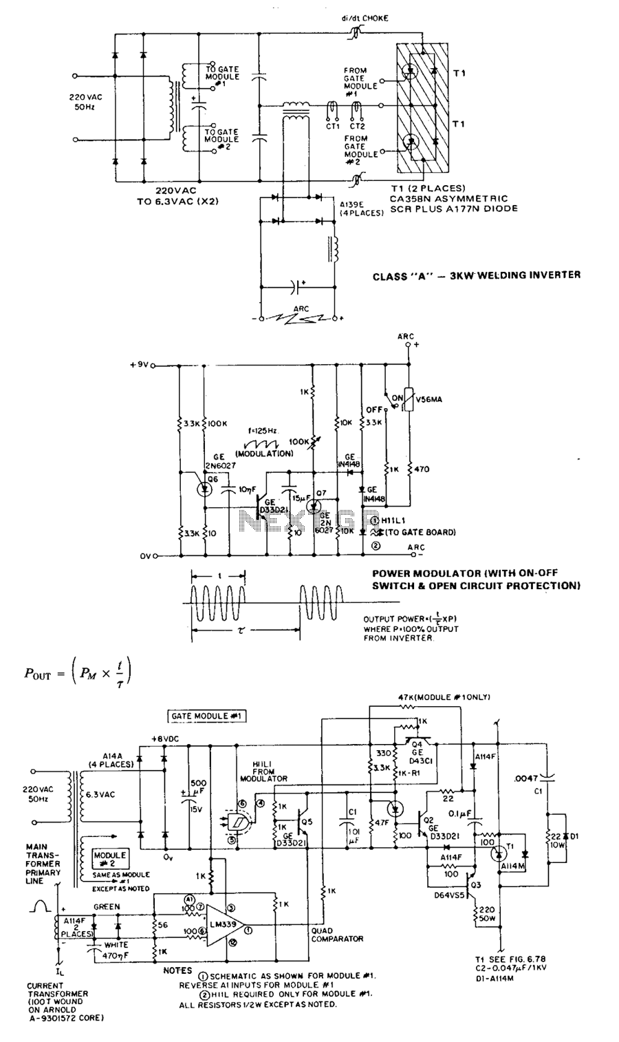
The Class A series resonant inverter is recognized for its high efficiency, low cost, and compact size, provided the operating frequency exceeds approximately 3 kHz. However, it faces challenges, particularly in high power versions, regarding the difficulty of achieving...
The TL494 controls a car's audio inverter power supply, which is a high-fidelity audio power supply designed for custom vehicles. It operates reliably without the need for adjustments according to the provided circuit diagram. The TL494 is a versatile integrated...
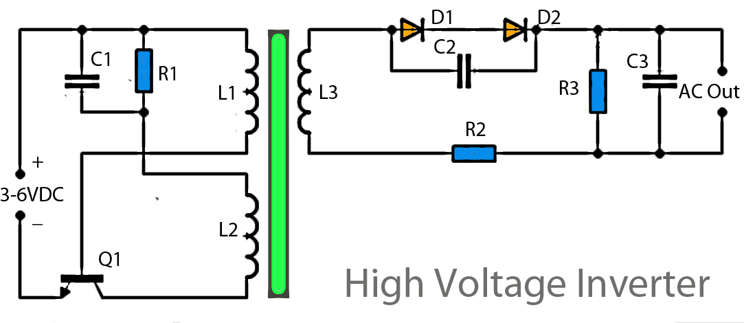
This inverter circuit operates using a transistor and transformer, along with other components, to elevate the voltage. The input supply voltage ranges from 3V to 6V DC, which is then converted to a high voltage AC output. However, the...