
H-bridge driving problemMOSFET frequently damage

The described circuit employs an H-bridge configuration using IRF740 MOSFETs to achieve DC to AC conversion. The H-bridge consists of four MOSFETs arranged in a bridge topology, allowing for the reversal of current direction through the load, thus generating an alternating current (AC) output from a direct current (DC) source. In this case, the input voltage is 315V DC, and the desired output is 230V AC.
The IRF740 is a high-voltage N-channel MOSFET with a maximum drain-source voltage of 400V and a continuous drain current rating of 9.2A. When designing circuits with such high voltages, it is crucial to ensure that the MOSFETs are adequately protected against over-voltage and over-current conditions. The frequent damage to the upper MOSFETs suggests that there may be issues related to gate drive signals, insufficient heat dissipation, or lack of protection against voltage spikes.
To mitigate these issues, several strategies can be employed. First, proper gate drive circuitry should be implemented to ensure that the MOSFETs are driven into saturation quickly and efficiently, minimizing the time they spend in the linear region where they can overheat. A gate driver IC designed for high-voltage applications may be beneficial.
Additionally, snubber circuits can be added across the MOSFETs to absorb voltage spikes that occur when the MOSFETs switch off. This can help protect the devices from transient voltages that could exceed their maximum ratings. Furthermore, thermal management is essential; using heat sinks or active cooling methods can help maintain the MOSFETs within their safe operating temperature range.
Lastly, it is advisable to examine the load characteristics and ensure that the circuit is not subjected to conditions that exceed the MOSFETs' ratings. Implementing current sensing and protection circuits can help prevent excessive current from damaging the components. By addressing these factors, the reliability of the H-bridge circuit can be significantly improved, reducing the likelihood of MOSFET failure.I`m using H-bridge with IRF740 (MOSFET) to convert 315VDC to 230VAC. But the upper mosfets are frequently get damage within few seconds. I can`t find.. 🔗 External reference
Related Circuits
This circuit operates with a 12V supply connected to a motor, utilizing transistors TIP 142 and TIP 147. Each transistor is controlled by a high (5V) or low (0V) signal through a 1kΩ resistor. The diodes used in the...
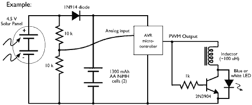
This example demonstrates the PWM (pulse-width modulation) output of a microcontroller controlling a Joule Thief style voltage booster to power a white LED. The circuit described utilizes a microcontroller to generate a PWM signal, which is an effective method for...
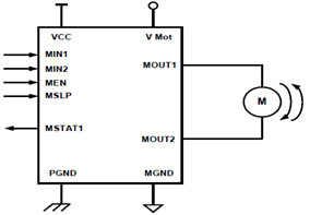
The schematic presented illustrates a 5A H-Bridge Module designed for the operation of a single Bipolar DC motor. The H-Bridge Module includes a header set (J2) and a connector terminal set (J1). Below is the pinout description for the...
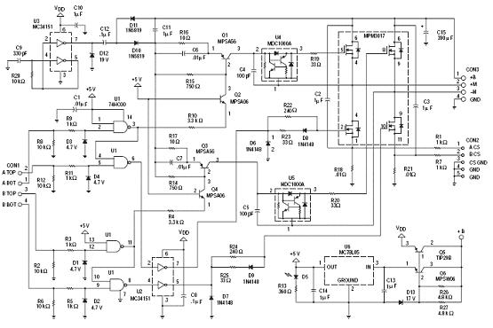
The following circuit illustrates an N-Channel H-bridge motor drive circuit diagram. Features include low voltage motor drives utilizing N-channel MOSFETs. The N-Channel H-bridge motor drive circuit is designed to control the direction and speed of a DC motor using low...
This is a driving relay circuit utilizing a 555 integrated circuit (IC). The circuit is designed to control a relay and prevent the 555 IC from becoming unresponsive by employing inductive feedback. The coil is safeguarded. The driving relay circuit...

A design for an H-Bridge has been created to control a 12VDC, 6 Amp motor. The circuit functioned effectively on a breadboard at 7.2 VDC while operating a small DC motor. The H-Bridge circuit is a crucial component in motor...