
DCF77 interface

The circuit design effectively facilitates the integration of the DCF77 time signal into a PC environment, leveraging the RS232 standard for communication. The use of the DTR and RTS lines ensures that the receiver is adequately powered while maintaining the integrity of the RS232 interface. The isolation of the monitor LED from the main circuit is a critical design consideration, as it prevents potential interference from high current surges that could disrupt the sensitive components of the receiver.
The BF244 JFET serves as a crucial component in establishing the necessary voltage reference for the DCF77 receiver, ensuring stable operation. The choice of a 1.5k ohm resistor in conjunction with the LED allows for controlled current flow, minimizing the brightness of the LED while providing sufficient voltage to the receiver.
The TL081 operational amplifier's role in converting the DCF77 signal to a format compatible with the RS232 standard is vital for reliable data transmission. The operational amplifier's configuration must ensure that the signal levels conform to RS232 voltage standards, facilitating seamless communication with the PC's UART. The timing specifications dictated by the DCF77 standard are essential for accurate data representation, and the adjustments made for safe reception are a testament to the careful design considerations taken to ensure reliable operation.
In summary, this circuit exemplifies a robust solution for interfacing a DCF77 receiver with a PC, showcasing thoughtful design choices that prioritize both functionality and protection against potential circuit issues. The combination of component selection and circuit configuration allows for effective communication and reliable time signal reception.The circuit interfaces a commercial DCF77 receiver (available for about $15) with a PC using the RS232 serial port. By rewriting the program and/or modifying the circuit it`s possible to use also different systems or different I/O ports.
The power is driven from three lines of the RS232 port (that is full protected against short circuits and there fore there is no risk of damaging it). The DTR and RTS lines are set high (+12V on the port) and the TXD is kept low ( 12V) for the power supply of the receiver. The RTS line gives positive power to the circuit and the DTR powers only the monitor LED that is kept separated from the rest of the circuit because of its high current peaks.
The BF244 JFET, the 1. 5k © resistor and the second LED compose a voltage reference of about 1. 8V needed for powering the commercial receiver. Only a very low current flows through this LED won`t be particularly bright. The TL081 sends the DCF77 signal (RS232 compatible) on the RXD pin. This pin must always be high ( 12V since this pin is inverted on the RS232) and go low one per second (when a bit is received). The DCF77 standard imposes a pulse time of 200ms for high bit and a of 100ms for low bit, but, since receivers usually use about 40ms for a safe reception these times are reduced to 160 and 60ms.
When receiving this pulses with the PC UART 8250 (or better) at the speed of about 40 bit per second N81 a 160ms pulse will produce a $80 or a $C0 byte and a 60ms a $FE or $FC. 🔗 External reference
Related Circuits
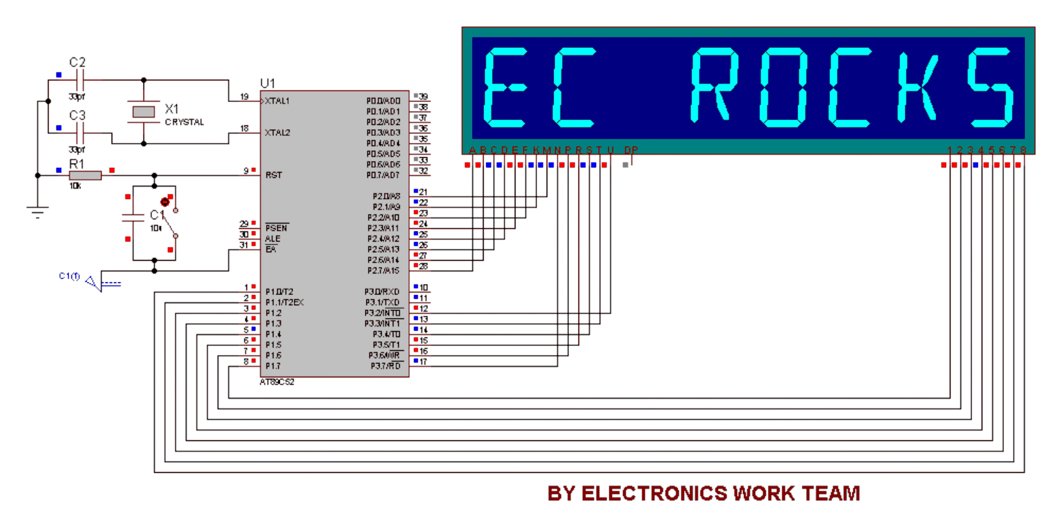
This circuit utilizes a 14-segment display to represent characters. The 14-segment display consists of 22 pins, which facilitate the display of various characters. Eight pins labeled A, B, C, D, E, F, K, and M are connected to the...
Audio can be extracted from a telephone line using a transformer and a capacitor to isolate the line from external equipment. A non-polarized capacitor is placed in series with the transformer line connection to prevent direct current from flowing...
This project involves controlling an AVR microcontroller (MCU) using Visual Basic 6. The applications of this circuit are numerous, enabling the creation of various devices that require control from a Personal Computer (PC) or any circuit that collects data...
Building circuits to interface an Amiga A1200 to a PC AT/ATX power supply and tower case. To create a reliable interface between an Amiga A1200 and a PC AT/ATX power supply and tower case, it is essential to design a...
This interface is needed to connect the phone to a PC, because the PC's serial port works with voltage levels between -12 and 12V (RS232 protocol) and the phone operates between 0 and 5V (TTL protocol). Don't even think...

Cable and xDSL modems are increasingly popular, leading to a need for designs that interface with existing telephones at subscriber locations. The subscriber line interface circuit (SLIC) within the modem must ring the phone and provide loop current during...