
Telephone Audio Interface Schematic

The circuit for extracting audio from a telephone line involves a well-defined arrangement of components to ensure proper function and safety. The transformer serves as a critical component, providing isolation between the telephone line and any external devices, thus protecting them from potential damage due to voltage surges or faults in the line. The non-polarized capacitor, positioned in series with the transformer, effectively blocks any direct current while allowing alternating current audio signals to pass through. This design is essential for maintaining the integrity of the telephone line's operational state.
The capacitor's voltage rating is particularly important; it must withstand not only the standard on-hook voltage but also the peak ring voltage, which can fluctuate based on local conditions. A conservative approach is to select a capacitor rated for at least 400 volts to ensure reliable performance across varying environments.
The output from the transformer is a low-level audio signal, typically around 100 mV. This signal is suitable for interfacing with high-impedance inputs, such as those found in audio amplifiers or recording devices. The use of a three-transistor amplifier can further enhance the audio signal, providing adequate gain for processing or recording.
To protect the circuit from potential overvoltage conditions, two diodes are strategically placed across the transformer’s secondary winding. These diodes serve to clamp the audio signal, preventing it from exceeding 700 mV peak during ringing signals, which is crucial for safeguarding downstream components from damage. The choice of diodes, such as the 1N400X, 1N4148, or 1N914, provides flexibility while ensuring robust performance.
Lastly, the inclusion of a 620-ohm resistor in the circuit design is vital for managing the load on the telephone line. This resistor acts to minimize loading effects when the output is connected to low-impedance devices, ensuring that the line remains functional and that the audio signal is not adversely affected. Overall, this circuit design effectively balances performance, safety, and compatibility with a range of audio processing equipment.Audio from a telephone line can be obtained using a transformer and capacitor to isolate the line from external equipment. A non-polarized capacitor is placed in series with the transformer line connection to prevent DC current from flowing in the transformer winding which may prevent the line from returning to the on-hook state.
The capacitor sho uld have a voltage rating above the peak ring voltage of 90 volts plus the on-hook voltage of 48 volts, or 138 volts total. This was measured locally and may vary with location, a 400 volt or more rating is recommended. Audio level from the transformer is about 100 mV which can be connected to a high impedance amplifier or tape recorder input.
The 3 transistor amplifier shown above can also be used. For overvoltage protection, two diodes are connected across the transformer secondary to limit the audio signal to 700 mV peak during the ringing signal. The diodes can be most any silicon type (1N400X / 1N4148 / 1N914 or other). The 620 ohm resistor serves to reduce loading of the line if the output is connected to very low impedance.
🔗 External reference
Related Circuits
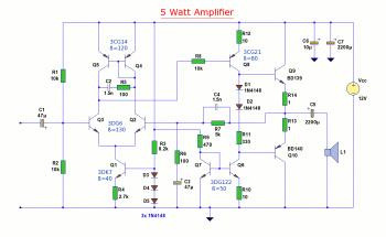
The diagram illustrates a 5W audio amplifier circuit constructed using power transistors BD139 and BD140 for the final amplification stage. This compact amplifier serves as a general-purpose amplifier suitable for applications such as computer audio, radio, MP3 players, and...

Is the battery empty, or is there something wrong with the device? This question often arises when troubleshooting a battery-powered device, such as a Walkman. When diagnosing issues with battery-powered devices, it is essential to systematically evaluate both the battery...
Read the generic sound level from an electret microphone. Several schematics utilize NPN transistors that yield an inverted output (~5V when quiet, ~0V when loud, with linear operation in between). However, a non-inverted output is desired, where a super...

The TDA8581(T) from Philips Semiconductors is a 1-watt Bridge Tied Load (BTL) audio power amplifier that can deliver 1 watt of output power into an 8-ohm load at a total harmonic distortion (THD) of 10% while using a 5V...
For many years, magnetic (or electromagnetic) water descaler devices have appeared on the shelves of home improvement and DIY stores across Europe. Despite numerous studies conducted by manufacturers and various consumer associations, none have definitively concluded on the effectiveness...
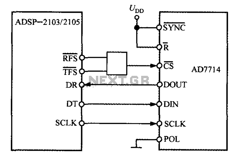
The ADSP-2103 and ADSP-2105 are digital signal processors that interface with the AD7714. When the output is active, the ADSP-2103/2105 configuration includes the RFS non-TES non-terminal set to a low level, while the SCLK terminal is configured for serial...