
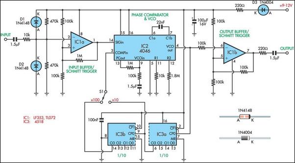
Decade frequency divider

The circuit configuration described involves a timing or filtering application where the values of resistors and capacitors are critical for achieving the desired frequency response or time constant. The relationship between the resistance and capacitance values is crucial, as the product of R2 and C2 is intended to be ten times that of the previous stage. This implies that if the previous stage's product is known, R2 and C2 must be selected accordingly to meet this requirement within the specified tolerance of ±2%.
R2 is specified to have a resistance value ranging from 27K to 10M, providing a flexible range for tuning the circuit's performance. The choice of R2 within this range will directly affect the time constant of the circuit, which is typically calculated as τ = R2 * C2. The capacitance C2, set at 0.047 µF (±1%), must be paired with an appropriate R2 value to ensure the product meets the tenfold increase requirement.
R1, with a resistance of 100K (±1%), serves as a biasing or loading resistor, impacting the overall impedance and stability of the circuit. The additional resistors R3 and R4, both set to 1K, may require adjustments to accommodate variations in the base resistance (Rbb) of the Unijunction Transistor (UJT). This adjustment is essential to maintain the desired operating characteristics of the UJT, which is often used in timing applications or oscillators.
Overall, the careful selection and adjustment of these components are vital for ensuring the circuit operates within the specified parameters, achieving the intended functionality while accommodating component tolerances and variations.In the next stage, the product of R2 and C2 should be 10 x that of the preceding stage (±2%). R2 should be between 27K and 10 M Cl & C2-047 µf (±1 %) R1-100K (±1%) R2-1M (±1%) R3—R4—IK (may need to be adjusted for variation of Rbb of UJT).
Related Circuits
This circuit utilizes the versatile MAX038 function generator. While some advanced features of this IC are disabled in this configuration, it is capable of generating sine, triangle, and square waves by adjusting the A0 and A1 pins (refer to...
When designing bass reflex loudspeaker cabinets, it is essential to measure the speaker's resonance with an accuracy of approximately 1%. This requires an audio oscillator and a frequency counter. However, the accuracy and resolution of a frequency counter when...
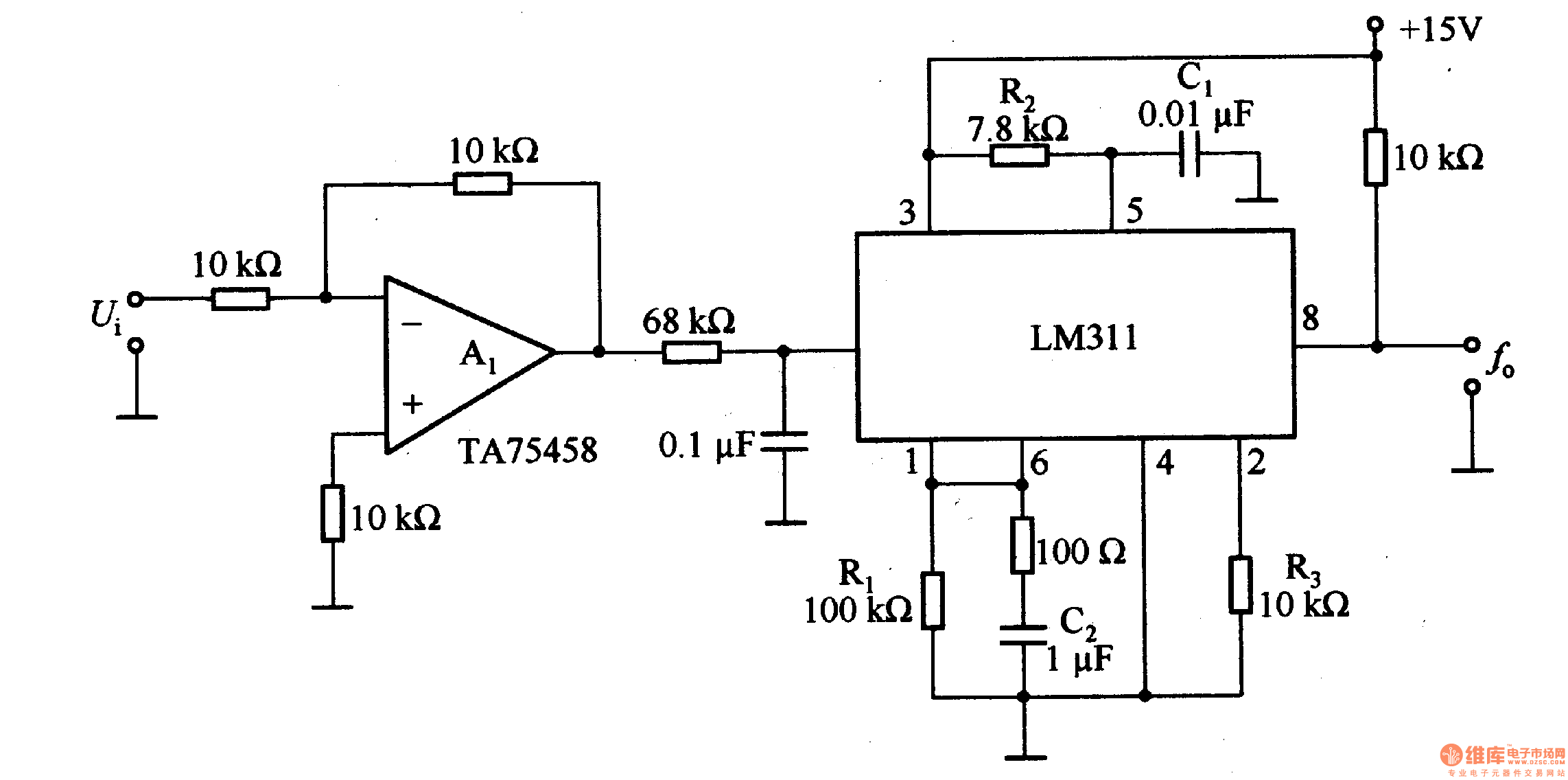
The LM311 is an integrated circuit that functions as a reference voltage generator, comparator, amplifier, and discharge circuit. It is designed for ease of use. In the circuit, the output frequency f0 is... The LM311 is a versatile integrated circuit...
A 0 to 2 MHz frequency meter with a Minimum Mass Wireless Coupler, based on the ATMega8. Range to the Minimum Mass Base Unit is 10 to 15 cm. Since the frequency meter is battery operated, it can be...
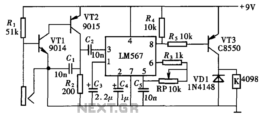
The electronic lock circuit is based on the frequency characteristics of the LM567 audio decoder. This circuit utilizes the audio decoding feature of the LM567, which outputs a low signal when the input signal frequency matches the oscillation frequency...
This calculator computes the resistor and capacitor values for a NE555 timer chip configured as an astable multivibrator (oscillator) or square wave generator. By entering the desired duty cycle and frequency, the calculator provides suitable values for the resistors...