
decibel meter circuit

The decibel meter circuit, or VU meter, is a valuable tool in audio systems for visualizing signal strength. This circuit typically utilizes an LM324 operational amplifier, which serves dual purposes: as a comparator to assess the input signal level and as an amplifier to enhance the signal for accurate representation. The circuit design allows for the integration of multiple LED indicators that light up in response to varying signal levels, providing a clear visual cue of audio intensity.
The input stage of the circuit is connected directly to the output of the audio amplifier, ensuring that the decibel meter accurately reflects the audio signal being sent to the speakers. The circuit is powered by a 12V DC supply, which is standard for many audio applications. The use of a variable resistor, VR500K, is critical for tuning the sensitivity of the meter. By adjusting this resistor, users can calibrate the circuit to respond appropriately to different signal levels, ensuring that the meter provides a meaningful representation of audio output without distortion or clipping.
Furthermore, the design can be adapted for various applications, such as in powered speakers or standalone audio amplifier systems. The simplicity of the circuit allows for easy assembly and integration into existing audio setups, making it an ideal project for both hobbyists and professional audio engineers. The visual feedback provided by the decibel meter enhances the user experience, allowing for real-time monitoring of audio levels and ensuring optimal performance of the audio system.The series of decibel meter function to determine the level of signal strength that is given to the speaker on the audio system. Decibel meter circuit is often also known as the VU meters on audio hifi system. For a series of decibel meters in this article displays strong technique with signal lights and LED. Decibel meter input circuit is taken f rom the output of the audio system that will connect to the speakers. The series uses a decibel meter this fruit as a comparator LM324 IC and 1 level amplifier with gain control. The series of decibel meter or VU meter is quite simple to make and circuit details can be seen in the following figure.
The series of decibel meters above requires 12VDC voltage source and an input signal from the audio power output that is connected to the speakers. The series of decibel meters can be installed on powered speakers or other audio amplifier system. To adjust the audio signal reception sensitivity is set by adjusting the value VR500K which serves as feedback and reinforcement factors will affect the amplifier circuit ahead of the decibel meter.
🔗 External reference
Related Circuits
This circuit produces a two-tone effect similar to the cuckoo song. It is suitable for use in doorbells or other applications due to its integrated audio amplifier and loudspeaker. When utilized as a sound effect generator, it can be...
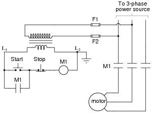
The most challenging aspect of interpreting ladder diagrams, particularly for individuals familiar with electronic schematic diagrams, is the representation of electromechanical relays. The operation of a motor control circuit should be explained, detailing what occurs when the "Run" switch...
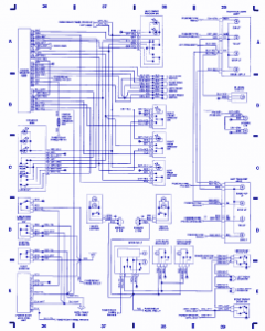
Emergency lights, fuse/relay panel, fresh air blower switch, engine control module, ignition coil, console switch, power windows, ABS control unit, ABS hydraulic unit, instrument cluster, taillight, headlight switch, automatic solenoid, ignition switch. The described circuit encompasses multiple essential components for...
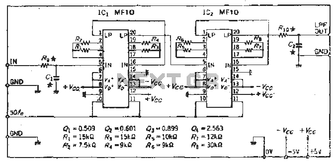
To create a Butterworth low-pass filter with a 12 dB/octave roll-off, four second-order (12 dB/oct) filter blocks are connected in series. This configuration is intended to achieve flat response characteristics across the frequency spectrum. The values for each stage...

When the system is placed in a shop or mall, logos and product advertisements serve as an ideal complement to temperature information. For home use, photographs of children at the beach or, should the temperature drop, images of making...
The preamplifier is safeguarded against excessive input signals of either polarity by utilizing the 2N5909 junction field-effect transistor. A nulling circuit allows for the adjustment of the preamplifier output voltage to zero at a fixed low level (up to...