
Cutoff frequency 48dB-octSCF low-pass filter circuit
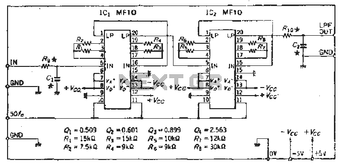
The described circuit utilizes a Butterworth low-pass filter design, known for its maximally flat frequency response in the passband. The series connection of four second-order filters results in a total of 48 dB/octave attenuation beyond the cutoff frequency, which is beneficial for applications requiring sharp frequency roll-off.
The design considerations include selecting appropriate resistor and capacitor values to achieve the desired cutoff frequency. The cutoff frequency (fc) can be calculated using the formula:
fc = 1 / (2πRC)
where R is the resistance and C is the capacitance of each filter stage. The distribution of values across the four stages allows for fine-tuning of the filter response and ensures that the transition between passband and stopband is smooth.
To address potential issues with signal integrity, the output stage must be designed to minimize distortion. The integration of a low-pass filter at the input stage serves to suppress high-frequency noise, enhancing the overall S/N ratio. If the input signal contains a wide frequency spectrum, an active filter configuration may be necessary to maintain the integrity of the desired signal while effectively attenuating unwanted frequencies.
Power supply considerations are also crucial, with the circuit requiring a stable +5V supply for optimal performance. The clock frequency settings indicate a need for flexibility in the design to accommodate varying operational conditions, ensuring that the circuit can adapt to different input signal characteristics without compromising performance.
In conclusion, the design of this Butterworth low-pass filter circuit is aimed at achieving a high-quality signal output while addressing common challenges associated with clock signal distortion and noise interference. Proper selection of components and careful configuration of the filter stages will result in an effective solution for applications requiring precise frequency filtering.In order to obtain wax dB / oct low pass filter of Butterworth times, the four 12dB / oct (2-order filter) block were four series, in order to obtain the flat characteristics of tanks, the opening value at all levels will be distribution, the value of the circuit from the mouth small block start sequence, they worked out the parameters of heart SCF disadvantage is that the output clock signal is multiplied, so SlN deteriorate, additional input signal frequency will close off the clock frequency Diego, noise, the output, the input circuit must be added to a low-pass filter. This circuit uses a simple passive filters to improve the S / N, if the input signal has a very wide frequency spectrum shall be added to the positive regulation of active filter.
Determined cutoff frequency. The clock frequency can lead to 12 to select, lead wire connected to + sv 12, the required clock frequency 50j inches, when connected ov, need 100f. The upper limit of the clock frequency is iMHz, so it is easy to form 20 kHz h. 1, the low-pass filter.
Related Circuits
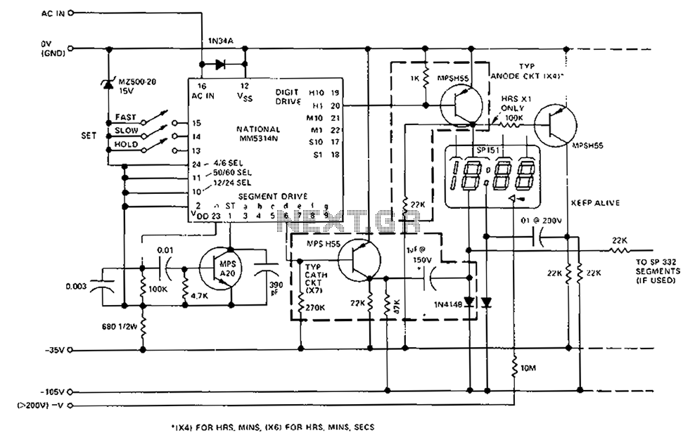
A CMOS clock circuit is capable of driving a multi-digit gas discharge display. This simple circuit does not include an alarm feature but allows for a flashing colon to indicate morning and afternoon. The circuit requires seven drive circuits...
This integrated circuit (IC) requires fewer external components, making it simpler for beginners to assemble it on a veroboard. The original circuit was sourced from its datasheet. A slightly modified version of the circuit is presented below. This circuit...
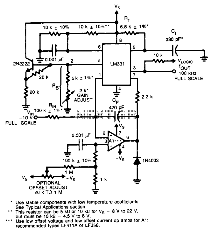
This circuit utilizes a conventional operational amplifier in conjunction with a feedback capacitor (CF) to perform integration. When the output of the integrator exceeds the nominal threshold level at pin 6 of the LM131, it triggers the timing cycle....

This circuit delivers an initial voltage of 2.5V per cell to rapidly charge a car battery. The charging current decreases as the battery charges. This circuit is designed to provide an efficient charging solution for car batteries by applying an...
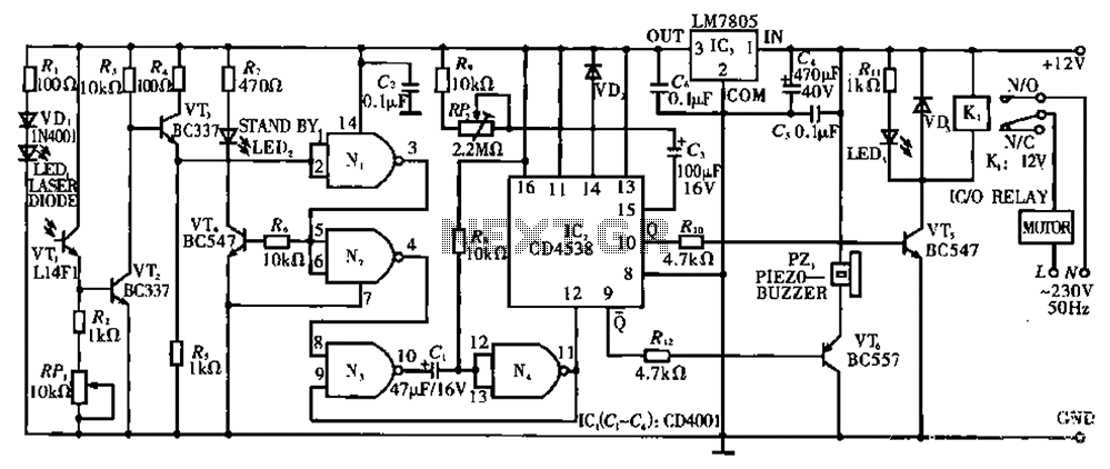
Circuit T operates on the principle of utilizing a laser diode LED as a light emitter. This circuit incorporates a laser diode that serves similar functions as a light-emitting diode. It features a resistor (R) and a diode (VD)...
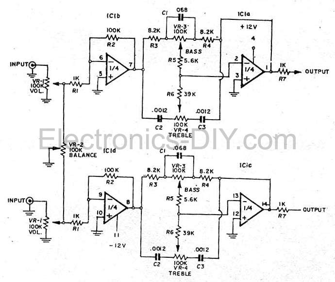
This simple tone control (bass and treble control) can be utilized in various audio applications. It can be integrated into amplifiers, function as a standalone control module, or even be incorporated into new and innovative instruments. The circuit employs...