
Delay circuit diagram CC4017 counter divider consisting

The CC4017 is a decade counter and distributor that counts from 0 to 10, providing ten output states. It is commonly used in various digital applications for counting purposes, such as in timers, clocks, and event counters. The device operates on the principle of binary counting, where each output represents a specific count state.
The circuit diagram typically includes the CC4017 IC, which has ten output pins (Q0 to Q9) and a clock input. The clock input triggers the counting sequence, while the reset pin allows the counter to return to zero. The delay aspect of the circuit can be implemented using additional components such as resistors and capacitors, which form an RC timing circuit. This timing circuit can introduce a delay in the clock signal, allowing for controlled counting intervals.
In practical applications, the outputs of the CC4017 can be connected to LEDs to visually indicate the count or to other digital circuits for further processing. The use of the reset feature allows for the counter to be restarted at any time, making it versatile for various timing and counting applications. The design of the circuit must ensure that the power supply voltage is within the specified range for the CC4017 to function correctly, typically between 3V and 15V. Proper bypass capacitors should also be included to stabilize the power supply and prevent noise from affecting the performance of the counter. CC4017 count/distributor consisting of a circuit diagram of the delay:
Related Circuits
This index is organized alphabetically by each word (excluding prepositions). For instance, the "Frost Alarm" will be listed under both "A" and "F". To efficiently locate a circuit, utilize the top index or employ your browser's search feature. In...
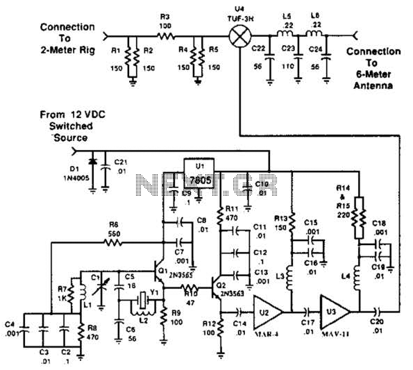
This transverter utilizes the bilateral properties of a balanced mixer to generate a 6-meter output from 2-meter inputs. The component Y1 is a 90-MHz crystal. It is important to note that the input frequency on the 2-meter band is...
The objective is to enhance information transmission through the distribution of articles. Please contact us via email at [email protected] within 15 days if there are any issues related to article content, copyright, or other concerns. Prompt deletion will occur...
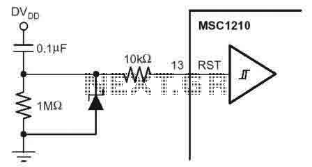
According to the MSC1210 datasheet, you will perform an external reset by taking RST pin high for two tOSC periods as this stops device operation, crystal oscillation, causes all digital pins to be pulled high from that point and...
The voltage to be sampled is applied to the input of R2, a 100K linear taper potentiometer, while the other end of R2 is grounded. Consequently, the signal level that is sent to the buffering level shifter U1-A and...
The circuit for the ball game scoring device is depicted in the accompanying image. This device records and displays the performance of a ball game. The first Nixie tube has two states: it can either be off or display...