
MSC1210 Reset Circuit

The external reset circuit for the MSC1210 is designed to ensure reliable operation of the device by providing various reset sources. The RST pin plays a critical role in this process. When the RST pin is driven high for a duration of two oscillator periods (tOSC), the device halts all operations and disables the crystal oscillator. This action also ensures that all digital pins are set to a high state, effectively preparing the device for a reset. Following this high state, the RST pin must be driven low to initiate the reset sequence.
In the typical reset circuit configuration, a 10 kΩ resistor is employed in series with the RST pin. This resistor serves as a pull-up mechanism, ensuring that the RST pin remains high when not being actively driven low. The reset circuit can be triggered by multiple sources, including power-on reset, which occurs when power is applied to the system, external reset triggered by an external signal, software reset initiated by the microcontroller, watchdog timer reset to recover from unresponsive states, and brownout reset to protect the system during voltage drops.
The schematic representation of this reset circuit is vital for engineers designing systems that incorporate the MSC1210, as it illustrates the connections and components necessary for effective reset management. The inclusion of the 10 kΩ resistor is particularly important for maintaining the integrity of the reset signal across various operating conditions. This design ensures that the MSC1210 and any connected microcontroller or memory components operate reliably, minimizing the risk of erroneous states due to improper reset conditions.According to the MSC1210 datasheet, you will perform an external reset by taking RST pin high for two tOSC periods as this stops device operation, crystal oscillation, causes all digitall pins to be pulled high from that point and then followed by taking the RST pin low that initiates the reset procedure. Herein a typical reset circuit of the MSC1210-a precision Analog-to-Digital Converter (ADC) with 8051 Microcontroller and Flash Memory schematic that can be done from the following sources: power-on reset, external reset, software reset, watchdog timer reset, and brownout reset. The figure (click to enlarge) shows a recommended external reset circuit for the MSC1210 with the serial 10kOhm resistor recomendation for any configuration of this reset type.
🔗 External reference
Related Circuits
This timer was designed primarily to turn off a portable radio after a specific duration. This feature allows users to fall asleep on the beach or in a hammock, with the assurance that the radio will automatically shut off...
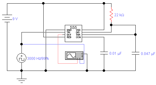
The standard assumption is that the phase shift sections operate independently. According to the equation provided, the loop phase shift reaches -180 degrees when the phase shift of each section is 60 degrees. This condition is met when ω...
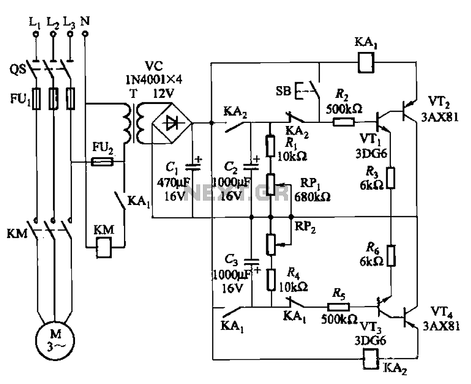
The circuit illustrated in Figure 3-79 consists of two delay circuits. The RPi adjustment potentiometer and RP2 can be modified to control the duration of the motor operation, allowing for arbitrary adjustments within a specified time frame. The circuit comprises...
The transmitter provides an optical link (infrared) for headphones. Three infrared LEDs (IR) are powered by T1, with P1 used to adjust the current level. The current consumption of this headphones infrared transmitter is approximately 60mA at 9V. The infrared...
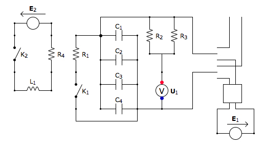
This is the discharging circuit. The red lines indicate the flow of energy from the capacitors to the terminals when the switch is in the upward position. The circuit is complete due to the connection of the terminals by...
An LED, or Light Emitting Diode, is a semiconductor device that allows current to flow in one direction while blocking it in the opposite direction. This characteristic makes LEDs polarized components, having a positive side known as the anode...