
Delayed Pulse Generator Circuit

The circuit comprises three 555 timer integrated circuits (ICs) connected in a specific configuration to achieve a delayed-pulse generation function. The first IC, designated as IC1, is configured in an astable mode, serving as a waveform generator. It produces a stable rectangular waveform that serves as the basis for the subsequent operations of the circuit. The frequency and duty cycle of this waveform can be adjusted by varying the values of the resistors and capacitors connected to IC1.
IC2 is configured in a monostable mode, which allows it to generate a single output pulse in response to a trigger signal. The output pulse duration is determined by the resistor R1 and the capacitor connected to IC2. This configuration makes IC2 crucial for creating the desired delay before triggering the next stage of the circuit.
IC3, also configured in a monostable mode, receives a trigger from IC2 on the trailing edge of the pulse generated by IC2. The output pulse width from IC3 is controlled by resistor R2 and an appropriate capacitor. The combination of R1 and R2 allows for fine-tuning of both the delay time and the pulse width, enabling a significant range of operation, up to a 10:1 ratio.
The circuit's design allows for versatility in applications requiring delayed activation or timing sequences, making it suitable for various electronic projects. Proper selection of component values will ensure the desired performance characteristics are achieved, providing a reliable and adjustable delayed-pulse generator. Three 555 IC timers are used in this circuit to construct a simple delayed-pulse generator. IC1 acts as a waveform shaper to produce a rectangular waveform. IC2 produces a delaying pulse to trigger 103 on the trailing edge of the delaying pulse. Rl controls delay time and R2 controls pulse width. As much as a 10:1 range can be generated.
Related Circuits
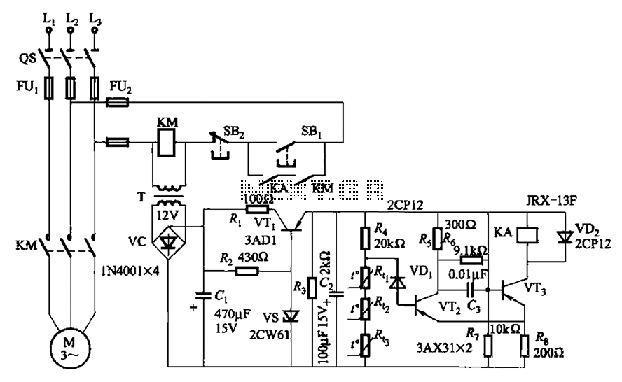
A P-type transistor (VT2, VT3) and other components form a common emitter-coupled trigger, functioning as a Schmitt trigger device. This setup serves as a switching circuit to detect changes in the resistance of a PTC thermistor, thereby controlling the...
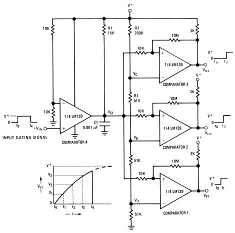
A measure delay generator, also identified similarly to a sequence generator, is a device that provides output signals at specified time intervals from a time reference. It automatically resets when the input signal returns to ground. The schematic illustrates...
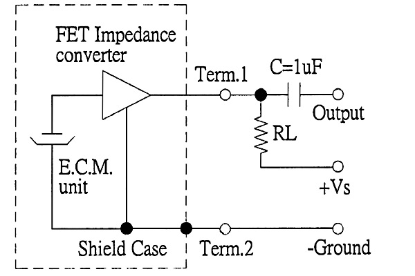
The back of the electret microphone resembles the drawings of the CUI Inc part number CMA-4544PF-W, which will be included in the parts kit. While debugging the data logger software on Windows, an oscilloscope practice lab was conducted using...
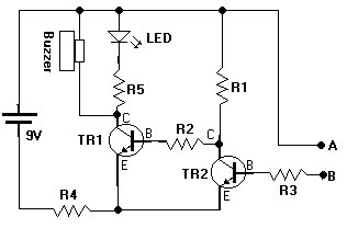
This document presents a water sensor circuit designed to monitor soil moisture levels for plants. This circuit is straightforward and is constructed using five resistors, two transistors, an LED, a buzzer, and a battery. The operation of the circuit...
A thermistor is utilized in the circuit for heat sensing, while two 5K variable resistors are incorporated to calibrate the circuit for activating the relay at the desired temperature. The inclusion of a 1N4007 diode across the relay serves...
Introduction The MIC2290 is an internally compensated standard step-up switching regulator that features an integrated power switch and Schottky diode. The inclusion of these components makes the MIC2290 an optimal solution for 48V Avalanche Photo Diode (APD) applications. In...