
water detector circuit for your

The water sensor circuit functions as a basic moisture detection system. It utilizes two transistors configured as a switch, which controls the buzzer and LED indicators. The circuit operates on a low voltage battery, ensuring it is energy-efficient and suitable for continuous use in a garden or indoor plant setting.
When the soil moisture level drops below a certain threshold, the resistance in the soil changes, triggering the transistors. This change activates the buzzer, producing an audible alert to indicate that the soil is dry. The LED serves as a visual indicator, providing a clear signal that attention is needed for the plant's watering.
The resistors are used to set the biasing conditions for the transistors and to limit the current flowing through the buzzer and LED, ensuring that they operate within safe limits. The choice of components allows for a compact and reliable design that can be easily assembled on a breadboard or a printed circuit board (PCB).
In summary, this water sensor circuit is an effective tool for plant care, combining simplicity in design with functionality to ensure plants receive adequate moisture. It is an excellent project for beginners in electronics, demonstrating fundamental principles of circuit design and component interaction.Today i want to share with you all my water sensor. This is my second successful project when i started with electronic hobby. This circuit is useful for your plant. How it`s work simple. It will beeping when your plant soil is dry and stop when it detect water. that all. It hard Don`t worry, it`s simple circuit construction. You just need 5 re sistors, 2 transistors, a LED, Buzzer and battery of course. Ok let`s construct the circuit. 🔗 External reference
Related Circuits
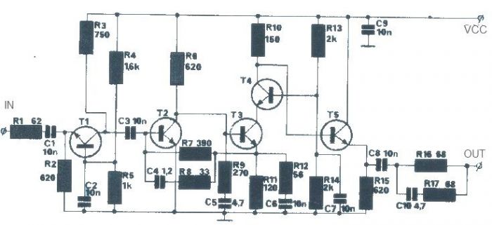
The T1 transistor must be of the BF200 type (or a similar variant), while the other transistors can be of the BF214 type. To achieve high efficiency, the antenna amplifier should be positioned at a short distance from the...
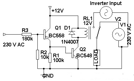
Three weeks ago, an inverter circuit diagram was introduced; however, the circuit did not include the AC to inverter switching part. Today, a 230 Volt AC to inverter switching circuit diagram is being presented. The circuit demonstrates inverter switching....
It's a very simple circuit, for the follow-up of baby. It can however be also used for other use, as intercom etc. In the place of M1 we can we use a simple electret mic capsule. The regulation of...

This circuit is a module for a diesel and horn train system. It is constructed using a 555 timer IC and several operational amplifiers (op-amps). The circuit serves as a complete system for the horn function. The main power...

This is a low-cost FM antenna booster designed to enhance reception of programs from distant FM stations. The FM antenna booster circuit features a common-emitter tuned RF preamplifier utilizing the VHF/UHF transistor 2SC2570 (C2570). The schematic illustrates the configuration...
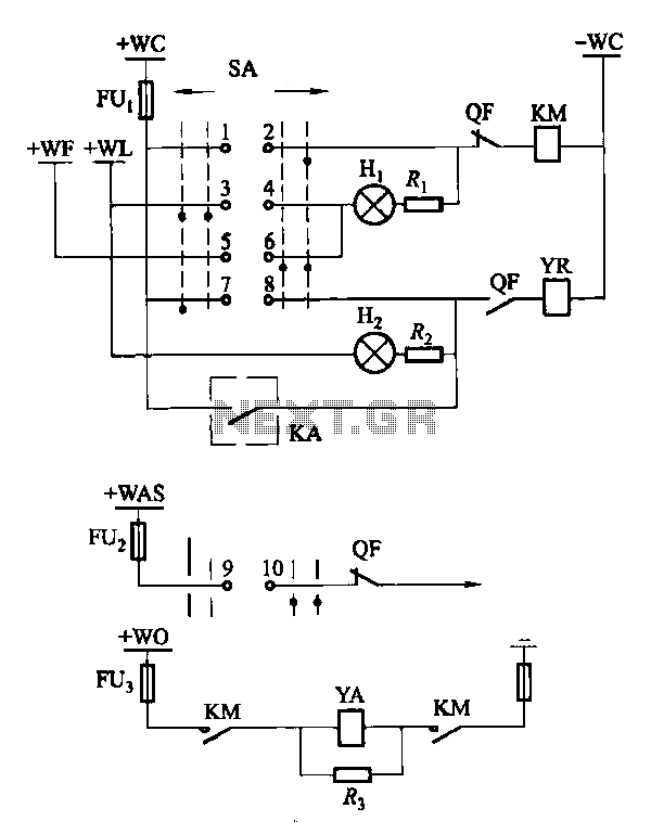
Factories and enterprises operating at voltages of 10 kV and below commonly utilize the CD10 (formerly CD2) type electromagnetic actuator as a circuit breaker. This mechanism features a mechanical anti-jump device. The control signal circuit for the CD10 actuator...