
Deluxe Charge Rate Limiter for Small Capacity NiCad Batteries

The dual battery charging circuit operates on the principle of limiting the charge current to prevent overheating and potential damage to the batteries. It incorporates two identical charging paths, each designed to handle one battery pack. Each path includes a series resistor to limit the current, ensuring that the charging rate remains within safe limits as dictated by the specifications of the batteries being used.
The circuit is powered by a standard wall charger that outputs approximately 55mA. This output is split between the two battery packs, allowing for efficient charging without exceeding the maximum current capacity of the wall charger. It is critical to select appropriate resistors to achieve the desired charging current for each battery. The resistors should be calculated based on the voltage drop across them and the target charging current, ensuring that each battery receives its designated 27mA.
Protection features may also be included in the design, such as diodes to prevent reverse current flow and ensure that the batteries do not discharge back into the charger. Additionally, capacitors can be added for smoothing the voltage and reducing ripple, further enhancing the reliability of the charging process.
Overall, this dual charger circuit is an effective solution for charging two battery packs simultaneously while maintaining safe charging parameters, making it suitable for a variety of applications where space and power efficiency are paramount.Here is a deluxe version of the simple charge rate limiter, using the same idea but with the ability to charge two packs simultaneously from a single wall charger. For circuit description and parts list, see the simple charger page. Since wall chargers provide about 55mA, you should not use this dual circuit to charge batteries at rates greater th
an 27mA (for a total of 54mA). 🔗 External reference
Related Circuits
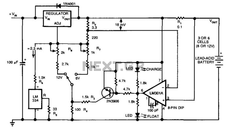
The circuit provides an initial charging voltage of 2.5 V per cell at 25°C to quickly charge a battery. The charging current decreases as the battery charges, and when the current falls to 180 mA, the charging circuit lowers...
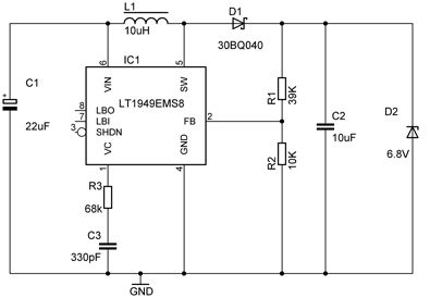
A portable phone charger designed for a Siemens mobile phone has been updated to include a printed circuit board (PCB), a USB connector, and enhanced current capabilities. The new charger utilizes a step-up converter based on the TPS61032, which...
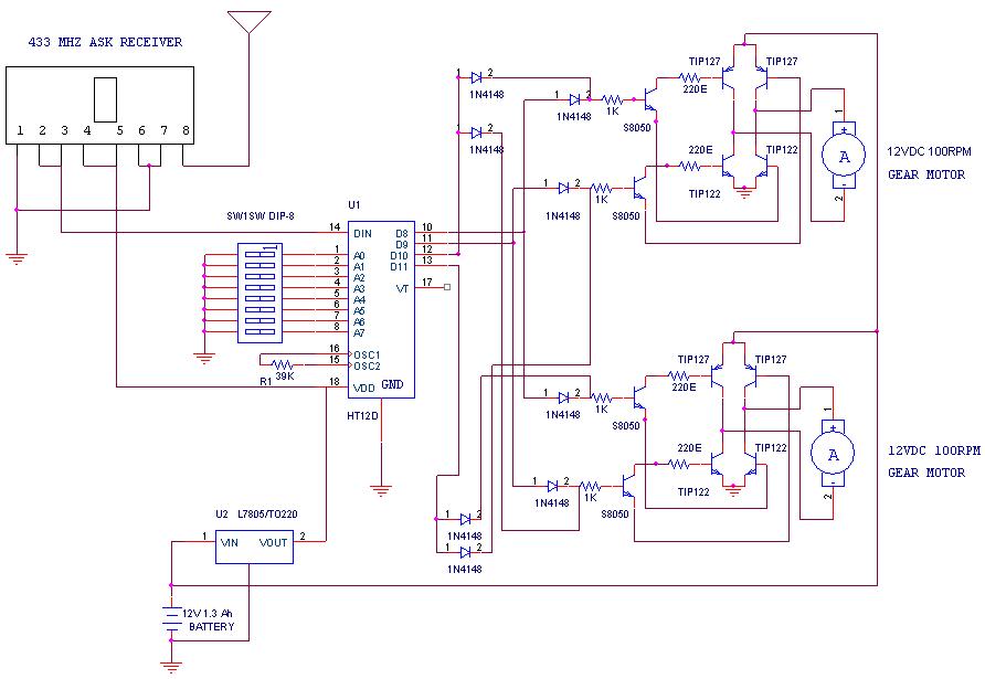
A remote-operated spy robot circuit can be controlled using a wireless remote controller. It captures audio and video information from the surroundings and transmits this data to a remote station via RF signals, with a maximum range of 125...
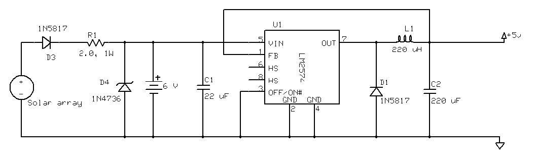
The project involved the use of three solar cells wired in parallel, accompanied by a large 4700 µF capacitor on a perf board. A total of 13 such assemblies were created, resulting in 39 solar cells and 13 capacitors,...
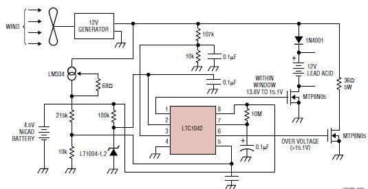
This simple wind charger circuit project is designed using the LTC1042 monolithic CMOS window comparator, manufactured by Linear Technology. The wind charger circuit utilizes wind power to generate the energy necessary for charging Ni-Cd or lead-acid batteries. When the...
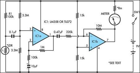
Strictly speaking, this simple circuit shouldn't work! How could anyone expect an ordinary light-dependent resistor photo cell to 'see through a fingertip? This circuit utilizes a light-dependent resistor (LDR), commonly referred to as a photoresistor, which changes its resistance based...