
Heart Rate Monitor

This circuit utilizes a light-dependent resistor (LDR), commonly referred to as a photoresistor, which changes its resistance based on the intensity of light it receives. The fundamental principle behind this circuit is the ability of the LDR to detect variations in light levels, which can be harnessed for various applications, including simple light sensors or more complex systems.
In this particular configuration, the LDR is placed in a voltage divider arrangement with a fixed resistor. When light falls on the LDR, its resistance decreases, which in turn alters the output voltage across the resistor. This voltage can be measured and used to trigger different actions based on predetermined thresholds.
For instance, when the light intensity exceeds a certain level, the voltage at the output may rise above a specific threshold, activating a connected device such as an LED or a relay. Conversely, in low light conditions, the resistance of the LDR increases, lowering the output voltage and potentially turning off the connected device.
The circuit can be powered by a standard voltage source, typically between 5V to 12V, depending on the specific components used. The choice of the fixed resistor value in the voltage divider is crucial, as it determines the sensitivity of the circuit. A lower value will make the circuit more responsive to changes in light levels, while a higher value will provide a more stable output in varying light conditions.
Overall, while the concept of using an LDR to detect light may seem straightforward, the circuit's functionality can be surprisingly effective, demonstrating the potential of simple electronic components to achieve complex tasks.Strictly speaking, this simple circuit shouldn t work! How could anyone expect an ordinary light dependent resistor photo cell to ‘see through a fingerti.. 🔗 External reference
Related Circuits
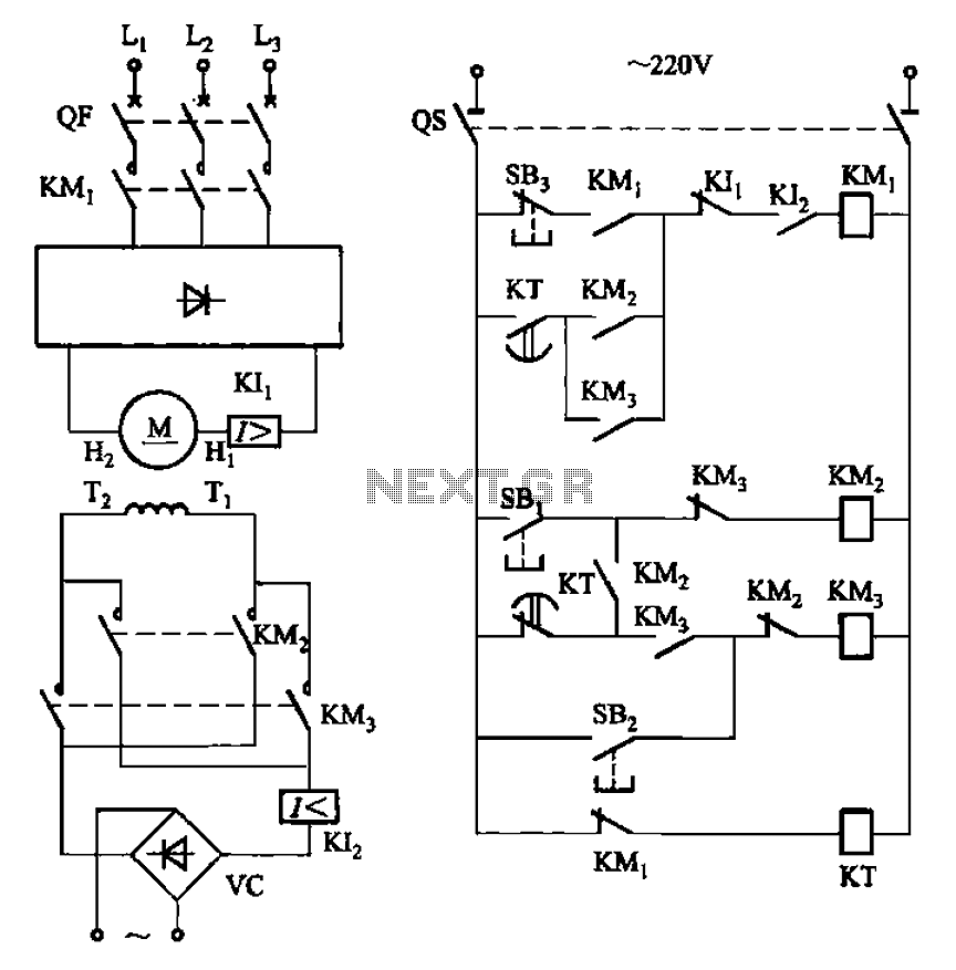
The circuit depicted in Figure 3-193 illustrates a separately excited DC motor. The brake circuit is not activated; therefore, positive reversals occur alternately using a delay action relay, ensuring that the motor reverses direction after coming to a stop. The...
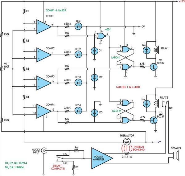
This circuit utilizes a 0.1Ω 1W resistor connected in series with the output of a power amplifier. When the amplifier delivers 100W into an 8Ω load, the resistor dissipates 1.25W. The temperature rise is detected by a thermistor thermally...
KA2213 is a single-chip record and playback integrated circuit produced by Samsung in South Korea. It is utilized in audio recording and playback devices. The internal circuit block diagram and pin functions of the KA2213 include a record and...
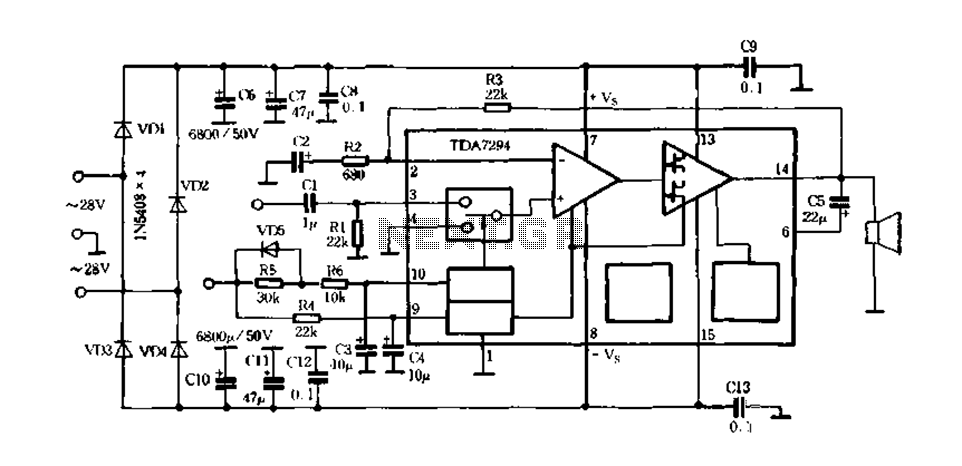
Europe's leading SGS-THOMSON STMicroelectronics recently introduced a new hydrazine fos power integrated amplifier, the TDA7294, to the Chinese mainland. This amplifier has surpassed traditional linear integrated amplifiers and has been successfully released for Hi-Fi applications, such as home theaters...
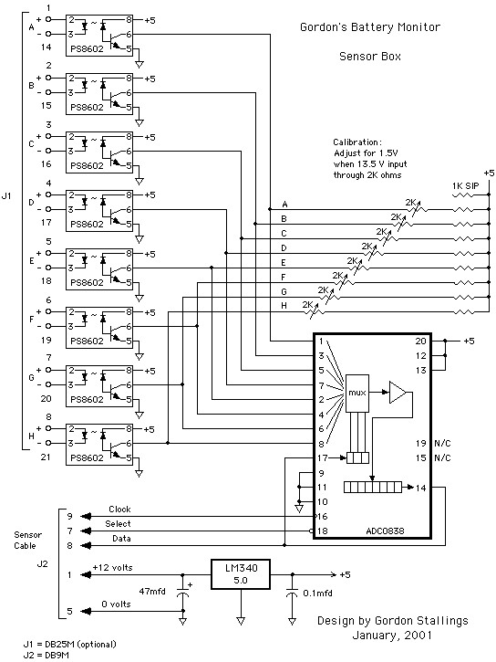
Figure 1 illustrates a schematic arrangement featuring four batteries. The diagram in Figure 2 employs a voltmeter and a two-pole multi-position rotary switch to select which battery to monitor. Although this design effectively moves the battery metering out of...
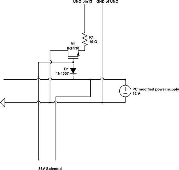
A 9 V DC battery initially powered the solenoid valve effectively. However, the solenoid did not generate sufficient force due to inadequate DC power. A modification was made to use a computer power supply as the power source. Providing...