
Design A Low-Cost 4- To 20-mA Receiver Circuit For Control Loops

The design of a low-cost 4- to 20-mA receiver circuit is essential in industrial applications for monitoring and controlling processes. This current loop standard is widely used for transmitting analog signals over long distances, where the 4-20 mA range represents the minimum and maximum values of the measured variable. The receiver circuit is responsible for converting the current signal into a voltage signal suitable for further processing, typically by an analog-to-digital converter (ADC).
To construct the 4- to 20-mA receiver circuit, several key components are required. The circuit typically includes a precision resistor (shunt resistor) to convert the current signal into a voltage drop. The value of this resistor is chosen based on the desired output voltage range. For instance, using a 250-ohm resistor will yield a voltage output of 1V to 5V for a 4-20 mA input.
The output voltage from the shunt resistor is then fed into an operational amplifier configured as a non-inverting amplifier. This amplifier provides the necessary gain to ensure that the voltage level is appropriate for the ADC. The gain can be adjusted by selecting appropriate feedback and input resistors. Additionally, filtering capacitors may be included to reduce noise and improve the stability of the signal.
The ADC converts the amplified voltage signal into a digital format for processing by a microcontroller or other digital processing unit. The choice of ADC is critical, as it should have sufficient resolution and sampling rate to accurately represent the input signal. Commonly used ADCs in such applications include successive approximation ADCs or sigma-delta ADCs, which offer high resolution and good performance in noisy environments.
Power supply considerations are also important in the design. The circuit should be powered by a stable voltage supply, and appropriate decoupling capacitors should be used to minimize power supply noise. Additionally, protection circuits may be implemented to safeguard the receiver from overvoltage or reverse polarity conditions.
In summary, the design of a low-cost 4- to 20-mA receiver circuit involves careful selection of components, including a shunt resistor, operational amplifier, and ADC, along with considerations for power supply and signal integrity. This circuit plays a crucial role in enabling effective control loops in industrial automation systems.Design A Low-Cost 4- To 20-mA Receiver Circuit For Control Loops | analog-to-digital converter (ADC). 🔗 External reference
Related Circuits
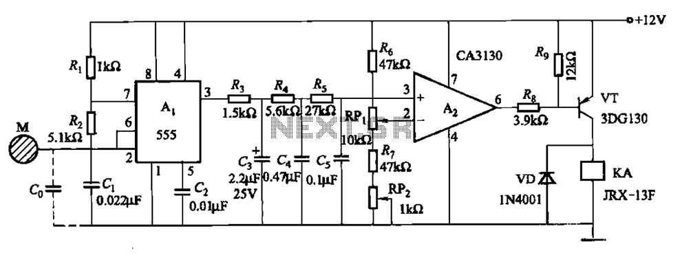
The circuit utilizes a 555 IC in conjunction with capacitors C1, C2, and a metal plate (tablet) M to create a distributed capacitance Co and resistor R1 connected to ground. Resistor R2 forms a self-excited multivibrator, while resistors R3...
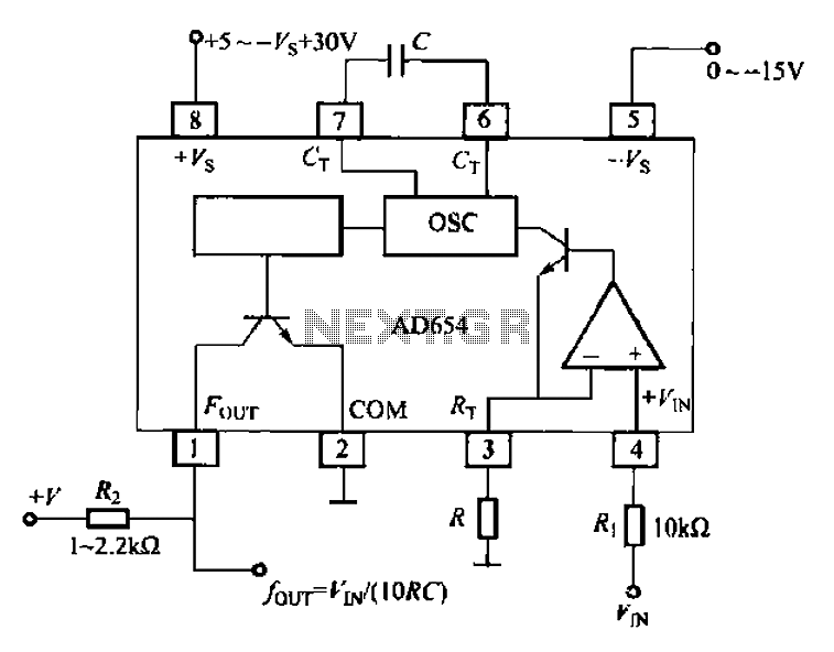
The AD654 voltage-frequency converter is a low-cost device that operates with a single supply voltage ranging from +5V to +36V, as well as with dual supplies of +5V to +18V. It can handle a maximum input voltage of 36V...
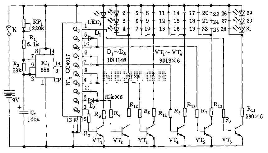
The circuit features a clock pulse generator and a pulse distribution circuit that drives the display circuit. It consists of a 555 timer and resistors RP1, R1, R2, along with capacitor C1, forming an astable multivibrator. The oscillation frequency...
This circuit turns off an amplifier or any other device when a low-level audio signal fed to its input is absent for at least 15 minutes. Pressing P1 switches the device on, supplying power to any appliance connected to...
AVC - The circuit regulates the volume line automatically, providing an output voltage of approximately 4 volts peak to peak. This voltage remains consistent. The Automatic Volume Control (AVC) circuit is designed to manage audio levels dynamically, ensuring a stable...
Firstly because of the modulation process we generate at least two copies of the intelligence plus the carrier. For example consider a local radio station transmitting on say 900 Khz. This frequency will be very stable and held to...