
AVC Automatic Volume Control Circuit

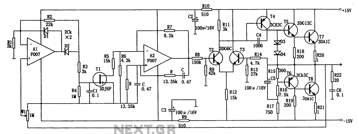
The Automatic Volume Control (AVC) circuit is designed to manage audio levels dynamically, ensuring a stable output that enhances the listening experience. The circuit operates by monitoring the audio signal and adjusting the gain as necessary to maintain a predetermined output level, in this case, around 4 volts peak to peak.
The AVC circuit typically consists of several key components, including operational amplifiers, resistors, capacitors, and diodes. The operational amplifiers serve as the main processing units, amplifying the audio signal while also providing feedback for automatic adjustment. The resistors and capacitors are used to set the time constants of the circuit, determining how quickly the AVC responds to changes in the input signal.
In operation, the circuit first detects the incoming audio signal's amplitude. If the amplitude exceeds a certain threshold, the AVC reduces the gain to prevent distortion and maintain a consistent output level. Conversely, if the signal amplitude is lower than the threshold, the circuit increases the gain to ensure that the output remains at the desired level.
The design of the AVC circuit can vary depending on the specific application and requirements. For instance, in a high-fidelity audio system, additional filtering may be incorporated to minimize noise and improve sound quality. In contrast, a simpler design may suffice for basic applications where audio quality is less critical.
Overall, the AVC circuit plays a crucial role in audio systems by providing automatic volume adjustment, enhancing user experience, and protecting against sudden volume spikes that could damage speakers or impair sound quality.AVC - The featured circuit controls a volume line automatically. It delivers an output voltage of approximately 4 volts peak to peak. This voltage remains.. 🔗 External reference
Related Circuits
The low-frequency signal generating circuit demonstrates excellent performance characterized by stable operation, high output power, and minimal waveform distortion. It serves as an ideal source for low-frequency measurement signals. The circuit includes an operational amplifier (A) with a feedback...
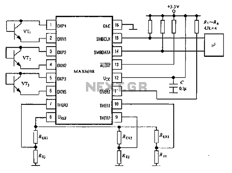
The circuit illustrated in the figure involves the MAX6698 maximum temperature sensor, which utilizes three transistors (VT1 to VT3) and three thermistors (RT1 to RT3). An internal reference voltage source is connected through resistors UREF REX1 to REX3, providing...
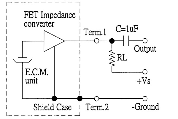
The back of the electret microphone resembles the drawings of the CUI Inc part number CMA-4544PF-W, which will be included in the parts kit. While debugging the data logger software on Windows, an oscilloscope practice lab was conducted using...
This circuit is used to power an LED with a voltage of 230V. The 230V must be reduced to meet the LED's voltage requirements. To achieve this, a circuit is necessary as described below. The circuit designed to power an...
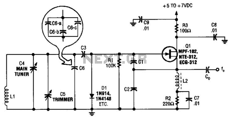
This basic VFO (Voltage Controlled Oscillator) operates within the 3 to 6 MHz frequency range and is commonly utilized in amateur radio applications, employing a Colpitts oscillator configuration. For operation at frequencies between 5 to 5.5 MHz, capacitors C2...
We have developed a powerful yet inexpensive and easy to construct experiment control system. The construction of the system together with the control software is described here. All circuits and software are free to download and use for nonprofit....