
development and evaluation for FPGA based systems
The Virtex-5 FPGA System Monitor is a sophisticated tool designed to enhance the reliability and efficiency of power management in FPGA applications. The integration of a 200 kSPS ADC within the System Monitor allows for high-frequency data acquisition, which is crucial for real-time monitoring of critical parameters such as temperature and voltage levels. The ability to monitor these parameters dynamically aids in identifying potential issues before they escalate into significant problems, thereby enhancing the overall robustness of the system.
The configuration of external channels for power monitoring is essential for ensuring that all relevant environmental factors are accounted for during operation. The guidelines provided for PCB implementation emphasize the importance of careful layout and design practices to minimize resistance and IR drop within the power distribution network. These practices are vital in maintaining the integrity of power delivery, particularly in high-performance applications where precision is critical.
The user-programmable features of the System Monitor, accessed via the DRP or JTAG TAP, facilitate a flexible approach to monitoring and control. This programmability allows designers to tailor the monitoring system to specific application requirements, optimizing performance and responsiveness. The automatic channel sequencing and filtering capabilities further streamline the monitoring process, enabling efficient data collection and analysis.
In conclusion, the Virtex-5 FPGA System Monitor represents a significant advancement in FPGA power management, providing essential tools for developers to ensure optimal performance and reliability in their designs. The combination of on-die measurement capabilities and user-configurable features positions the System Monitor as an indispensable resource in modern electronic design.With regard to the System Monitor feature presented in this article, Avalon Microelectronics used this feature in two Virtex-5 FPGAs (XC5VLX330T) in their development with great success. They had an unusual problem on their development board, which shut down when the FPGAs were performing certain functions.
Their power management so ftware caused the board to turn off due to certain power threshold violations. Using the Virtex-5 FPGA System Monitor, they were able to dynamically view where these violations were occurring and quickly find a solution. The issue turned out to be a simple miscalculation of a resistor value by their board vendor for one of the voltage regulators providing power to the FPGA.
They reduced our debug time by taking advantage of the built-in tools, without the use of expensive debugging equipment. Power consumption in electronic devices and the design of power systems is an increasingly complex task.
Static current levels coupled with increased dynamic current demands imply greater IR drops in power distribution systems. Operating temperature requirements require sophisticated heat sink and airflow measurements. The Virtex-5 FPGA System Monitor features on-die temperature and voltage measurement capabilities that provide valuable information for the development, evaluation, debugging, optimization, and qualification of PCB power designs.
This article explains how to configure System Monitor`s external channels for power monitoring and provides PCB implementation recommendations/guidelines. The Virtex-5 FPGA System Monitor has, as its core, a 200 kilo-Samples-Per-Second (kSPS) Analog-to-Digital Converter (ADC).
Fig 1 shows a block diagram of the System Monitor. The System Monitor allows unprecedented and convenient access to vital on-chip analog FPGA information. The inputs to the ADC are on-die temperature and voltage sensors. Using its 17 available external channels, the System Monitor provides for the measurement of the physical environment of the PCB or enclosure.
The control logic implements common monitoring features, including automatic channel sequencing, filtering, and alarms. All of these features are user programmable and can be customized at run time through the register file interface accessible in the FPGA logic through the Dynamic Reconfiguration Port (DRP).
The DRP is a standard bus interface available in many Xilinx FPGA blocks. This port enables updating the configuration of a particular block in a dynamic manner. Alternatively, the register file interface is accessed externally through the JTAG Test Access Port (TAP). Indeed, access to the System Monitor feature is available even before the device is configured using the JTAG TAP.
Increased current demands along with reduced power supply voltage complicate power system design by heightening the sensitivity to resistance in the power system. Reduced supply voltages imply reduced margin for inaccuracies in the power supply voltage. That is, the absolute value of the tolerable error scales with the power supply voltage itself. For example, the tolerance on the 1V VCCINT supply level is specified at ±5% or ±50mV. With a 5A current demand, an unaccounted series resistance of just 10 micro-ohms in the PCB power system, and a power supply nominally set to 1V, the DC level of the delivered power supply is already at its specified lower limit (i.
e. , 0. 95V due to the 50 mV PCB voltage drop between the regulator and the Virtex-5 device when 5A goes through the 10 micro-ohms PCB resistance). Modern BGA type packages make it virtually impossible to attach a physical probe to the ball of the device; consequently, the actual level of the power supply received by the FPGA is difficult to determine.
The System Monitor resolves this issue. For the first time, an accurate measurement of the actual on-chip power supply is made available and is simple to employ. The internal p 🔗 External reference
Related Circuits
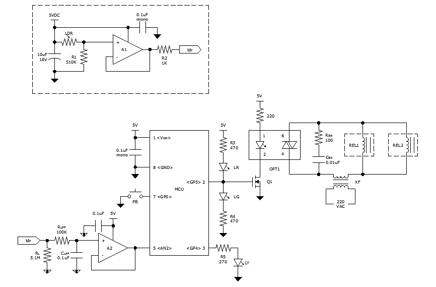
While discussing an all-linear automatic night light circuit, it was mentioned that an MCU-based Automatic Night Light Controller (ANLC) was being tested. The firmware has been tweaked since then. Recently, the sensor was installed outdoors and connected to control...

PICLink RS232 low-cost development controller with ADC. The PICLink RS232 embedded controller module provides any microcontroller with RS232 communication capabilities. The PICLink RS232 embedded controller is designed to facilitate communication between microcontrollers and RS232 devices, making it an essential component...
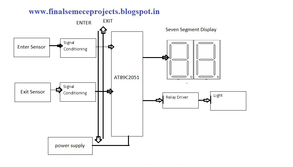
This project involves an automatic room light controller with a bidirectional visitor counter using a microcontroller. It is designed to manage room lighting and accurately count the number of individuals present. When a person enters the room, the counter...
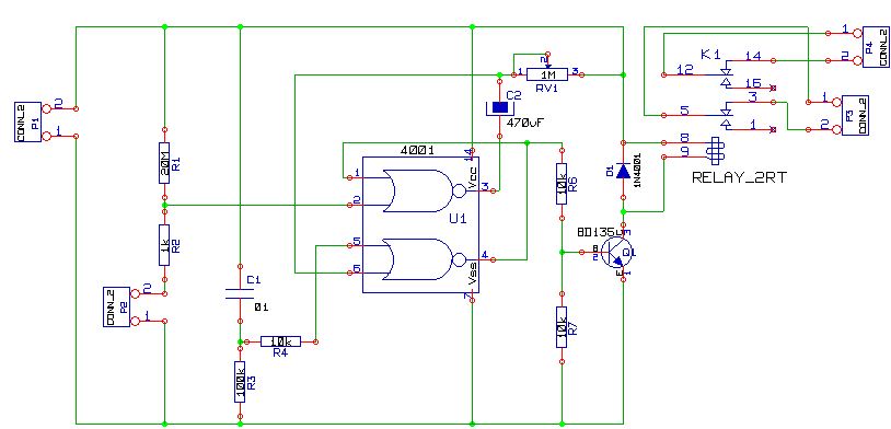
This is a simple alarm circuit using a CD4001 integrated circuit. It is designed for home, motorcycle, car, or other applications. The circuit will undergo computer simulation using Livewire, followed by printed circuit design with KiCad. SW1 is a...
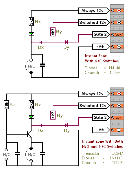
The SCR Burglar Alarm System allows for the addition of multiple extra zones. The primary circuit is designed for typical normally-closed input devices, including magnetic reed contacts, micro switches, foil tape, and passive infrared (PIR) sensors. An additional circuit...
Switching to alternative power sources can lead to savings on electricity bills. The photovoltaic module or solar panel discussed here has a power output of 5 watts. Under full sunlight conditions, the solar panel generates 16.5V and can provide...
Warning: include(partials/cookie-banner.php): Failed to open stream: Permission denied in /var/www/html/nextgr/view-circuit.php on line 713
Warning: include(): Failed opening 'partials/cookie-banner.php' for inclusion (include_path='.:/usr/share/php') in /var/www/html/nextgr/view-circuit.php on line 713