
Audio CD4001 based on Car Alarm Circuit

The alarm circuit utilizes the CD4001, which comprises four two-input NOR gates. The configuration of two NOR gates forms a bistable multivibrator, commonly referred to as a flip-flop. This arrangement allows the circuit to maintain its state until it receives an external reset signal, which in this case, is provided by the normally closed switch SW1. When SW1 is pressed, the state of the flip-flop changes, thus energizing the relay RL1.
The relay is essential for controlling higher power loads, as it acts as an electromechanical switch. The contacts of the relay can be configured to drive a siren and a light, providing both auditory and visual alerts when the alarm is triggered. The time constant for the circuit is determined by the values of R5 and C2, which can be adjusted to set the desired delay for the alarm activation.
In addition to the manual switch, integrating various sensors enhances the circuit's functionality. For example, a PIR motion sensor can detect movement within a specified range, while a smoke or gas detector can sense hazardous conditions, thereby activating the alarm without manual intervention. This versatility allows the circuit to be customized for different security needs, making it suitable for diverse applications such as residential security, vehicle protection, or industrial safety systems.
The design process includes simulation in Livewire to verify the circuit's behavior and performance before finalizing the layout in KiCad, ensuring that all components are correctly placed and connected for optimal operation. The printed circuit board (PCB) design will facilitate easy assembly and integration into the desired application, enhancing the circuit's reliability and effectiveness in providing security and alarm functions.This is a simple alarm circuit for a checkup with a 4001. It can be used to protect our home, motorcycle, car or any other application that comes to mind. In this circuit will be a computer simulation with Livewire and then design the printed circuit Kicad. SW1 is a normally closed switch when pressed triggers the flip-flop formed by the two NOR g ates of the CD4001 and remains there for a time determined by the time constant of R5-C2. This time it is keeping the relay RL1 and operated by its two contacts that investors control of two loads, for example, a siren and a light or any other that we connect to P3 and P4. We can replace the switch SW1 PIR motion sensor, an infrared barrier, a smoke detector, gas detector, a magnetic sensor, a panic button or other device to act as a closed switch and opened fire alarm.
🔗 External reference
Related Circuits
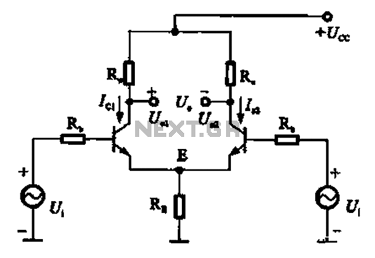
The common mode signal of an emitter-coupled differential amplifier circuit assumes that two equal small increases of the same polarity signal, referred to as the common mode signal, occur simultaneously. This results in an increase in the potential at...
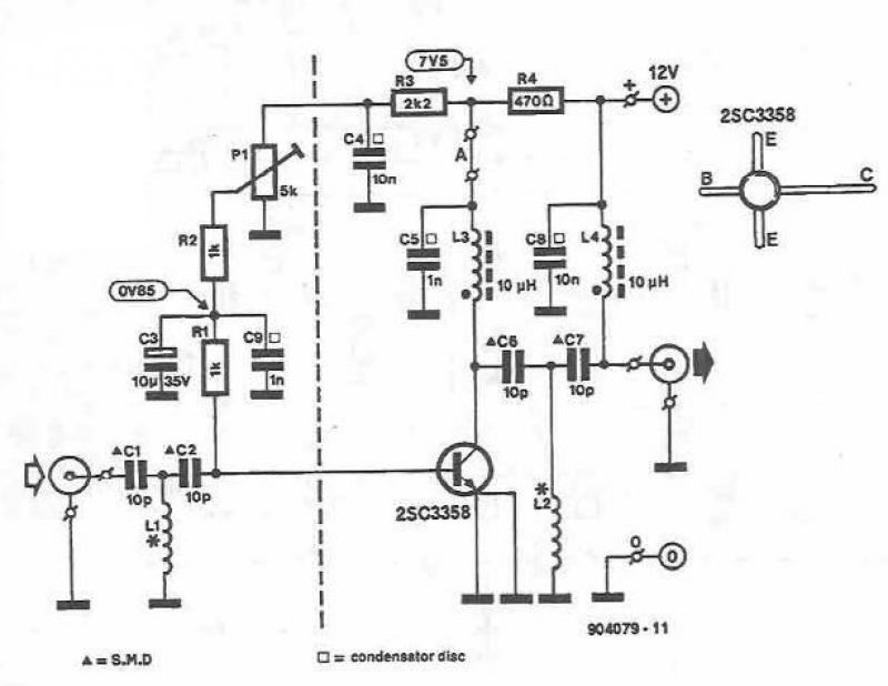
This UHF amplifier circuit project is beneficial for enhancing weak TV signals. The amplifier provides a gain of 10-15 dB within a frequency range of 400 to 850 MHz. To ensure optimal performance and reliability, the PCB tracks should...
This circuit features automatic Exit and Entry delays and a timed Bell Cut-off. It has provision for both normally-closed and normally-open contacts, and a 24-hour Personal Attack/Tamper zone. It is connected permanently to the 12-volt supply and its operation...
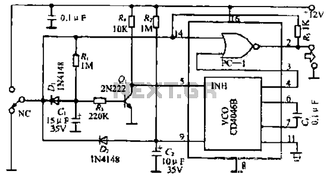
The figure illustrates a circuit involving dark tomb electric locks, specifically the fti: al: 4046B and XOR gate as the primary control mechanism. It emits pulses and utilizes silicon for successive pulse generation. The circuit operates with a normal...
The automatic sprinkler controller circuit consists of a power supply circuit and a humidity measurement and control circuit, as illustrated in the accompanying figure. The power supply circuit includes a power transformer (T), rectifier diodes (VD1 to VD4), filter...
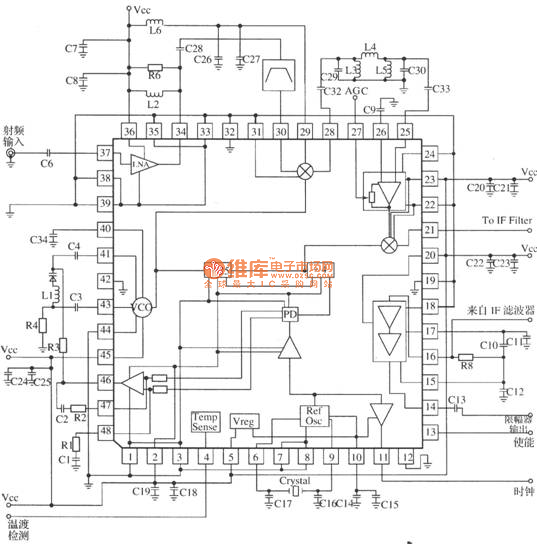
MRFICl505R2 is a 1.575GHz GPS downconverter chip. It integrates a mixer, VCO, PLL, crystal oscillator, A/D converter, loop filter, and other circuits. The MRFICl505R2 IF output frequency is 4.1MHz, with a typical conversion gain of 105dB, an operating voltage...