
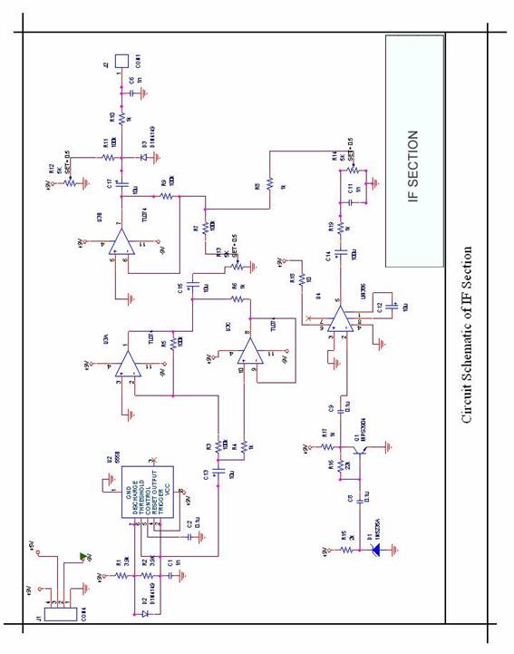
diagram shows rather simple voltage

The voltage stabilizer circuit operates by continuously monitoring the output voltage and comparing it to predetermined reference levels using operational amplifiers. When the output voltage deviates from the set thresholds, the op-amps trigger the SSRs, which in turn switch the transformer taps to either increase or decrease the output voltage. This feedback mechanism ensures that the output voltage remains stable despite fluctuations in the input voltage.
The design includes multiple presets (P1 to P7) that allow for fine-tuning of the tripping points, enabling customization for different load requirements and voltage conditions. The SSRs provide a fast switching capability, which is essential for maintaining voltage stability in applications where power demands may vary rapidly. The choice of SSRs also contributes to the overall reliability and efficiency of the circuit, as they can handle high currents with minimal heat generation compared to traditional electromechanical relays.
Additionally, the transformer used in the circuit is equipped with multiple taps, allowing for a range of output voltage levels. The selection of the appropriate tap is determined by the SSRs based on the feedback received from the op-amps. This dynamic adjustment capability is crucial for protecting sensitive electronic equipment from voltage fluctuations that could lead to damage or operational inefficiencies.
Overall, this voltage stabilizer design is well-suited for applications requiring robust power handling and precise voltage regulation, making it an effective solution for a variety of industrial and commercial environments.The diagram shows a rather simple voltage stabilizer design which can hold huge output power in the order of 5 to 10KVA. The use of SSR or solid state relays makes the output stage easy to configure and very accurate - thanks to the modern SSRs which are designed to trigger massive power in response to smaller input DC potentials.
The proposed circuit of a simple 5 KVA to 10 KVA automatic voltage stabilizer circuit is easy to understand. All the opamps are arranged in standard voltage comparator modes. The presets P1 to P7 can be adjusted as per the required tripping points, which will correspond to the output SSR switching and the subsequent transformer tap selections. These TAPs are chosen by the appropriate SSRs in response to the varying AC voltages, thus adjusting the output voltage to the appliances close to normal levels.
🔗 External reference
Related Circuits
Obtain more information about the circuit diagram of a mobile jammer by visiting this link. A GSM jammer, or cell phone jammer, is a device that transmits signals on the same frequency used by the GSM system. The effectiveness...
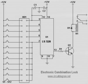
This circuit diagram represents a simple electronic combination lock utilizing the IC LS7220. The circuit is designed to activate a relay for controlling any device (on and off) each time a specific combination of four digits is entered. It...
Renewable energy discussions encompass various alternative energy, renewable energy, and free energy technologies. Discussions about environmental issues, global warming, and other related topics are also welcome. It is important to address the validity, organization, and general advice concerning the...

The audio circuit depicted in the figure is commonly utilized in color television systems. The pin functions and reference voltages for the TA8218AH are as follows: Pin 1: 1.9V - inverting input; Pin 2: 2.1V - R-channel audio signal...

A function generator virtual oscilloscope designed using a sound card serves as a multi-functional device, incorporating a microcontroller-based function generator. This project represents the implementation of a graduation thesis. A function generator typically generates various voltage waveforms, such as...
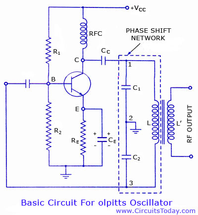
Colpitts oscillator circuit diagram and theory. Colpitts oscillator frequency equation. Colpitts oscillator using transistor. Colpitts oscillator using op-amp. The Colpitts oscillator is a type of electronic oscillator that generates sine waves and is widely used in various applications such as...