
Digital circuits

The LM555 timer is a versatile integrated circuit widely used in various applications, including oscillators, timers, pulse generation, and signal conditioning. It operates in two primary modes: astable and monostable. In astable mode, the LM555 functions as an oscillator, generating a continuous square wave output. The frequency and duty cycle of the output waveform can be adjusted by varying the external resistors and capacitors connected to the timer.
The astable oscillator calculator simplifies the design process by allowing engineers to compute the necessary component values to achieve desired frequency and duty cycle specifications. The capacitor calculator aids in selecting appropriate capacitance values to ensure stable operation.
In monostable mode, the LM555 timer produces a single output pulse in response to a triggering event. This mode is particularly useful for timing applications where a precise duration of output is required. The integration of triggering and timing helpers enhances the functionality of monostable timers, allowing for easy configuration and reliable operation.
Advanced circuits utilizing the LM555 and LM556 timers can include complementary or push-pull outputs, which enable efficient driving of loads such as LEDs or motors. Interlocked monostable timers provide additional control features, allowing for complex timing sequences.
Moreover, the LM555 can be employed as a voltage comparator or Schmitt trigger, expanding its application range. The adjustable 50% duty cycle feature allows for fine-tuning of pulse widths, making it suitable for specific timing needs.
Additional applications include bipolar LED drivers, electronic time constant control, and voltage-controlled pulse width oscillators, demonstrating the LM555's flexibility in diverse electronic designs. The 555 monostable circuit and the 555 timer in astable mode exemplify the foundational use cases of the LM555 timer, making it an essential component in the field of electronics.555 timer circuits LM555 - Astable Oscillator Calculator + Capacitor Calculator, Basic Circuits For The LM555 Timer, Triggering And Timing Helpers For Monostable Timers, Controlling Circuits For LM555 Timers, Advanced Circuits For The LM555 Timer, LM556 Timers with Complimentary or Push-Pull Outputs, Interlocked Monostable Timers, Power-Up Reset F or Monostable Timers, Cross Canceling For Monostable Timers, RS - Flip-Flop Made With A LM556 Timer, Using The LM555 As A Voltage Comparator Or Schmitt Trigger, LM555 With A 50% Duty Cycle (Adjustable), Bipolar LED Driver, Electronic Time Constant Control, Voltage Controlled Pulse Width Oscillator, . , 555 monostable circuit, 555 timer in Astable Mode 🔗 External reference
Related Circuits

This is a circuit design for a digital voltmeter with an LED display. It is suitable for measuring the output voltage of a DC power supply. The circuit features a 3.5-digit LED display with a negative voltage indicator and...
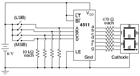
Digital circuits are circuits that handle signals restricted to binary states of zero and a maximum value. This is in contrast to analog circuits, where signals can vary continuously within the limits set by power supply voltage and circuit...
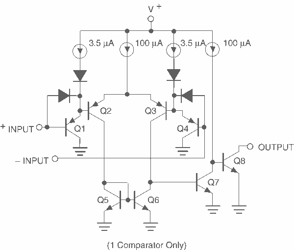
This page provides basic information about voltage comparator integrated circuits and is to act as reference material for other circuits. The circuits shown are based on the LM339 Quad Voltage Comparator chip or the LM393 Dual Voltage Comparator chip....
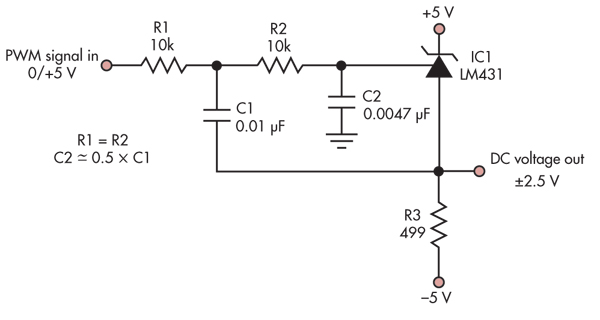
This simple circuit converts a 5V PWM signal into a variable precision reference voltage with a range of -2.5V to +2.5V. Many designs, such as a digitally controlled power supply or a programmable dummy load, require a Digital to...
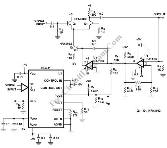
The Automatic Gain Control (AGC) is utilized in various systems, particularly in communications. This AGC operates at a frequency of 50 MHz, and the output voltage is determined by a required digital signal. The Automatic Gain Control (AGC) circuit plays...
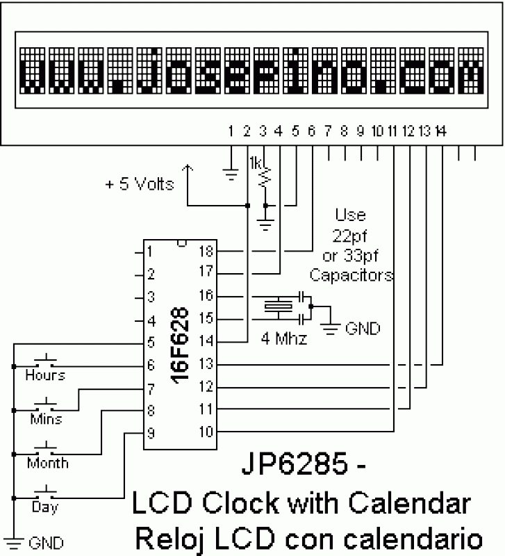
The reason why I am using an LCD display is because it allows me to display many characters and it doesn't need to be refreshed as 7-segment LED displays. Also, the interface requires less I/O pins. For this project,...