
digital clock in recycled retro-modern case

The schematic diagram serves as a visual representation of the electronic circuit, outlining the connections between various components such as resistors, capacitors, diodes, and the microcontroller itself. Microcontrollers are integral to modern electronic systems, acting as the brain of the circuit. They process input signals, execute programmed instructions, and control output devices.
In this design, the microcontroller likely interfaces with various sensors and actuators, which are essential for the system's operation. Input devices such as temperature sensors or switches can provide real-time data to the microcontroller, while output devices like LEDs or motors perform tasks based on the processed information.
Power supply considerations are also crucial in the schematic. The circuit must include a stable power source to ensure reliable operation of the microcontroller and other components. Bypass capacitors may be employed to filter out noise from the power supply, providing a clean voltage to the microcontroller.
Additionally, the layout of the schematic should prioritize signal integrity and minimize interference. Proper routing of traces and the placement of components can significantly impact the performance of the circuit. Ground planes may be used to reduce electromagnetic interference (EMI) and improve overall circuit stability.
In summary, while the schematic diagram and electronic assembly may appear straightforward, the complexity and functionality of the system are largely dictated by the microcontroller's programming and the careful design of the circuit.The schematic diagram (see picture) and electronic assembly are fairly straightforward since most of the magic happens in the microcontroller code.. 🔗 External reference
Related Circuits
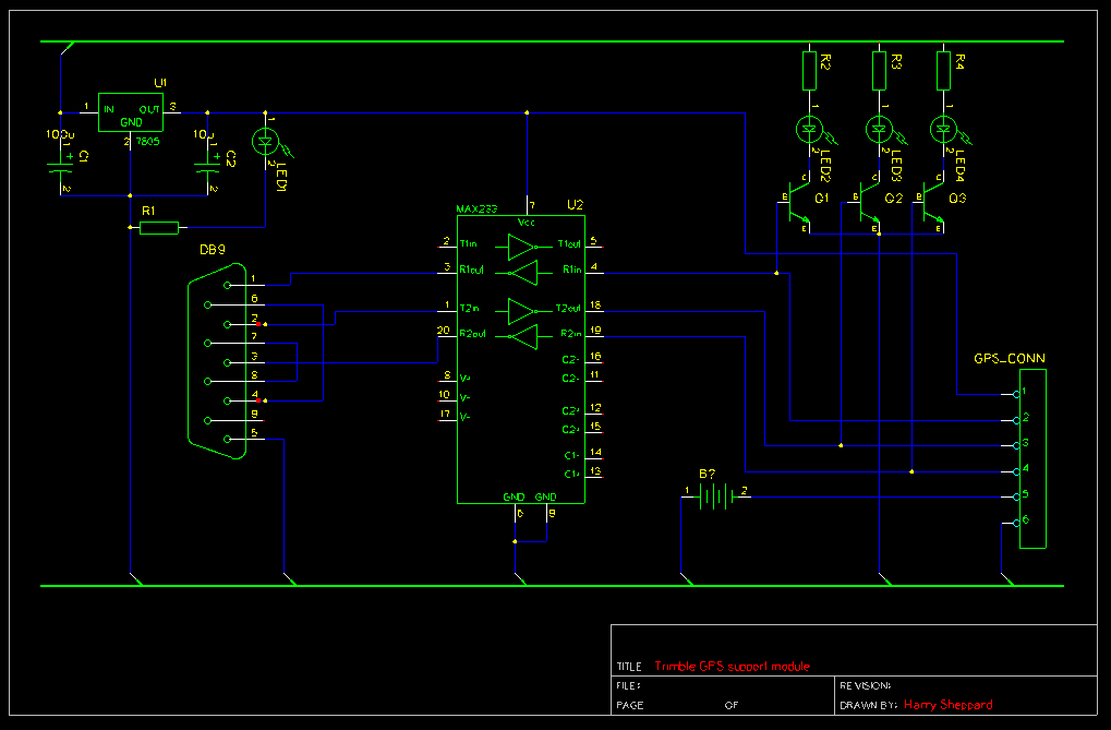
An L7805 voltage regulator provides a 5V rail. The input and output of the regulator are stabilized using a 470µF capacitor and a 10µF capacitor, respectively, to smooth the voltage supply. This 5V rail powers the MAX232 level shifter...

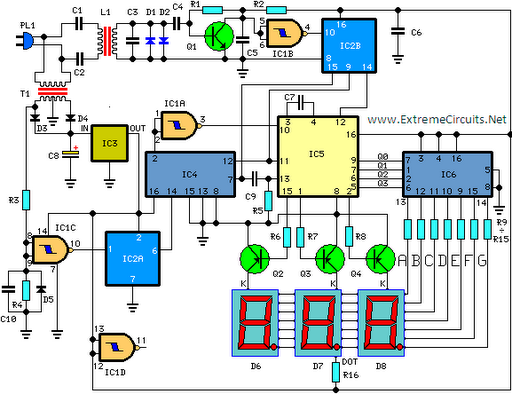
An FM and AM transmitter integrated into a compact device utilizing the CD4001 integrated circuit. It broadcasts at 20 MHz for AM and 100 MHz for FM. The described transmitter combines both Frequency Modulation (FM) and Amplitude Modulation (AM) capabilities...
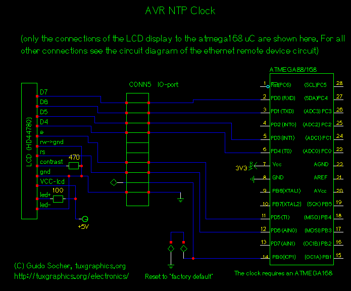
The Network Time Protocol (NTP) has transformed global timekeeping, allowing accurate time and date information from anywhere in the world. NTP is a straightforward UDP-based protocol that can be implemented in a microcontroller. While UDP and TCP servers have...

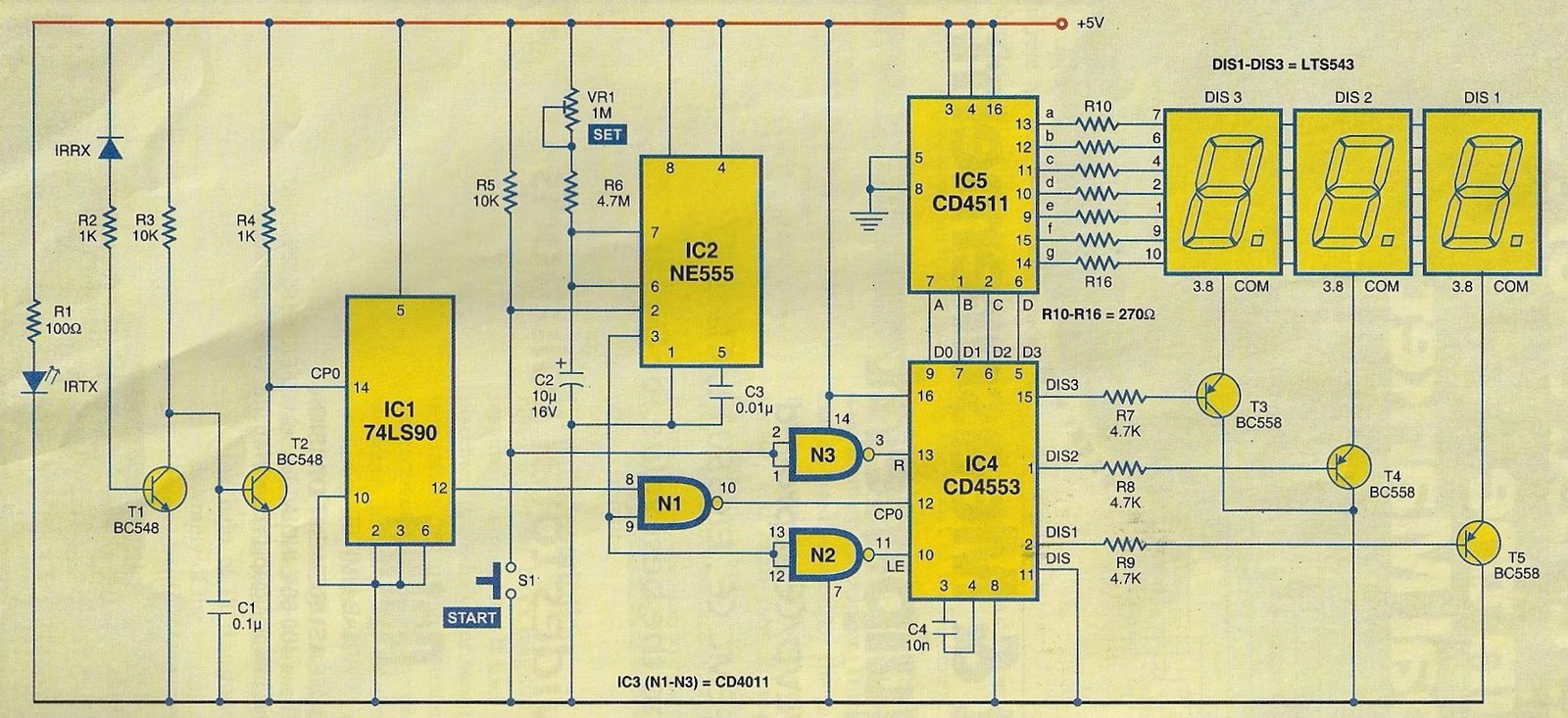
A digital stopwatch or digital timer circuit schematic is constructed using the timer IC LM555 and the 4-digit counter IC MM74C926, which is paired with a multiplexed 7-segment LED display. The digital stopwatch circuit utilizes the LM555 timer IC configured...
Measurement of physiological parameters such as heart rate and respiration rate is essential in the medical field. A simple method for measuring respiration rate utilizes a displacement transducer, which is fast and cost-effective. This method allows for the measurement...
This circuit is designed for precise measurement of temperature in degrees Celsius. It features a transmitter section that converts the output voltage from a temperature sensor, which is proportional to the temperature being measured, into frequency. The resulting frequency...