
DIGITAL RESPIRATION RATE METER

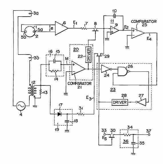
The described circuit integrates several key components for effective respiration rate monitoring. The displacement transducer serves as the primary sensing element, converting physical movement into an electrical signal. The IR transmitter and receiver assembly is pivotal for detecting the movement of the light ball, ensuring accurate pulse generation corresponding to each breath. The use of transistors T1 and T2 facilitates pulse processing, allowing for the clean transition between logic states that represent inhalation and exhalation. The configuration of IC 74LS90 and CD4553 ensures that the pulse counting is precise and displayed in a user-friendly format. The monostable multivibrator plays a crucial role in controlling the timing of the counting process, ensuring that the measurement window is fixed at one minute. This design provides a reliable and efficient method for monitoring respiration rates, making it suitable for various medical applications.Measurement of physiological parameters like heart rate and respiration rate is crucial in the field of medicine. Here is a simple method for respiration rate measurement using a displacement transducer. Its responds fast and is cost effective. By using this, respiration rate can be measured in the range of 0 to 999 respirations/ minute. Digital Respiration Rate Meter uses a displacement transducer for sensing the respiration rate using IR transmitter and receiver as shown in the physical assembly. Inhaling and exhaling the air during respiration causes a light ball to move up and down in a capillary glass tube.
This movement is sensed with the help of an IR transmitter-receiver assembly of the sensing circuit and converted into pulses through the pulse generator. These pulses are counted for a minute using a counter. The respiration rate is displayed on a 3-digit display through the seven segment decoder/driver. Start switch S1 is used to reset the display to zero and enable the counter for a minute to count the respiration pulse.
The gate pulse generator consists of a monostable multivibrator. When triggered by start switch, it generates gating pulse of one minute duration. The IR transmitter LED (IRTX) connected in series with resistor R1 transmits IR signals, which are received by the IR receiver LED (IRRX). The IR receiver is connected to the base of transistor T1 through Resistor R2. When the transmitted IR signal falls directly on the reverse biased IR diode, it produces an electrical signal according to the IR intensity.
So transistor T1 conducts and its collector goes low, which makes transistor T2 to cut off. Therefore the collector of transistor T2 becomes high, which represents logic 1`. When the IR signal from the transmitter is interrupted due to movement of the ball up and down during the inhale-exhale mechanism, transistor T1 is cut off and its collector goes high, which drives transistor T2 into conduction. The collector of transistor T2 goes low, which represents logic 0`. This means whenever the ball crosses the IR beam a pulse is generated during inhale and exhale. Two pulses are generated due to the ball crossing the IR beam twice: one during inhale and the other during exhale.
The final output of transistor T2 provides the clock pulse to IC 74LS90 (IC1). IC 74LS90 is configured as a divide-by-two counter and its output is used as the clock pulse for three-digit BCD counter CD4553 (IC4). The output of counter IC1 is connected to input pin 8 of NAND gate N1 of IC3. Input pin 9 of NAND gate N1 is connected to output pin 3 of monostable multivibrator IC2. The time period of the monostable is decided by resistor R6, preset VR1 is used to adjust the time period of the monostable to 1 minute.
When start switch S1 is pressed, pin 2 of the monostable goes low and it triggers to generate a pulse of one minute duration, which is fed to pin 9 of NAND gate N1. Therefore the gate is open for one minute to pass the clock pulses coming from IC1 to pin 12 of the three digit counter CD4553.
This one minute pulse of the monostable is inverted by NAND gate N2, which controls the latch enable (LE) of CD4553. When the monostable output goes high, the latch enable (LE) of CD4553 goes low and the counter advances.
When the monostable output goes low the latch enable (LE) of IC4 goes high and the counting stops. So there is no further change in the count shown on the 7-segment display. When start switch S1 is pressed pin 13 of CD4553 and the 7-segment display shows 000`. The CD4553 consists of three negative edge triggered BCD counters that are cascaded synchronously. A quad latch at the output of each counter permits storage of any given count. The information is then time-division-multiplexed, providing one BCD number or digit at a time. Digit-Select outputs provide display control. All the outputs are TTL-compatible. An on-chip oscillator provides low frequency sc 🔗 External reference
Related Circuits
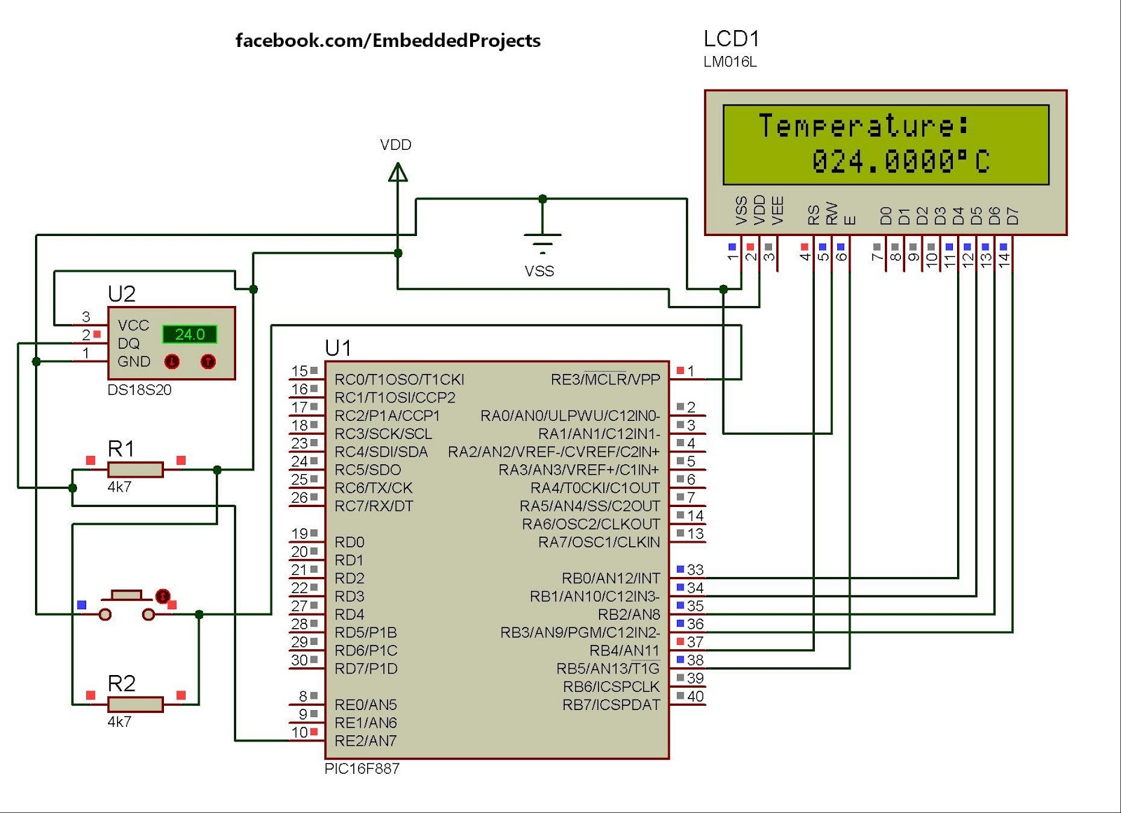
The hardware configuration for utilizing multiple 1-Wire temperature sensors, such as the DS1820, is straightforward. Communication between the microcontroller and the temperature sensors occurs over a single-wire bus. Additionally, it is possible to power the devices directly through this...
Electromagnetic flow meter: How to measure fluid flow using a magnetic field. An electromagnetic flow meter is a device used to measure the flow rate of conductive fluids by utilizing Faraday's law of electromagnetic induction. This principle states that when...
The tool is based on a NE555 (or LM555) timer i.c., wired as an astable multivibrator. The frequency of the multivibrator is determined by the value of the unknown capacitor Cx. The circuit can be fed by a small...
This is a straightforward tester designed to verify the fundamental operations of an infrared remote control unit. It is cost-effective and simple to assemble. The tester utilizes the infrared receiver module TSOP1738. The operation of the remote control is...
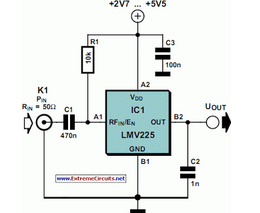
The National Semiconductor LMV225 is a linear RF power meter integrated circuit (IC) in a surface-mount device (SMD) package. It operates over a frequency range of 450 MHz to 2000 MHz. The LMV225 is designed for precise measurement of radio...
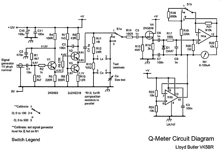
For many years, the Q meter has been an essential piece of equipment for laboratories engaged in the testing of radio frequency circuits. In modern laboratories, the Q meter has been largely replaced by more advanced and expensive impedance...