
Digital Clock with Solar Regulator


The clock circuit utilizes a combination of integrated circuits (ICs) to achieve timekeeping and display functionalities. The core of the system is a 32,768 Hz crystal oscillator, which provides a stable time base. This frequency is divided down by a 4020 binary counter to generate a half-second pulse, which is essential for accurate timekeeping. The first half of a 4013 dual D-type flip-flop is employed to further divide this signal, yielding a one-second pulse that drives the seconds counter, represented by the 74HC390 counter IC.
The minutes and hours are incremented based on the seconds counted. The clock logic decodes the accumulation of 60 seconds, triggering a reset of the seconds counter while simultaneously advancing the minutes counter. A similar method is applied for the hour counter, where the second half of the 4013 latch toggles to indicate AM or PM status based on the 12-hour format, resetting after 12 hours.
The display subsystem comprises an additional six ICs that decode the binary representation of time and drive four seven-segment LED displays. The tens of hours digit is controlled by a 3904 transistor, while two 4053 multiplexers allow for manual selection between minutes and seconds for the respective display digits. A dual-pole, double-throw (DPDT) switch facilitates the selection process, enabling the user to toggle between displaying seconds or minutes.
To manage the display's visibility, a set/reset latch constructed from 74HC00 NAND gates is included. This arrangement allows the display to be turned off completely, with a momentary switch controlling the latch. The run/stop switch plays a critical role in preventing accidental time adjustments while the clock is operational. It also activates the display during the stop mode.
The voltage regulation circuit ensures that the system operates at a stable 4.3 volts, derived from a 13.6-volt battery supply. A charge indicator LED provides visual feedback on the battery's charging state, illuminating only when maximum charge is being supplied. Once the battery reaches its nominal voltage, the regulator adjusts its output to maintain this level, turning off the charge indicator. Additionally, a four-LED battery condition indicator offers insight into the battery status, alerting users to potential issues with the regulator if the charge LED is off while fewer than four LEDs are lit. This comprehensive design ensures accurate timekeeping, user-friendly display management, and effective battery monitoring.The basic clock circuit (top schematic below) is similar to the binary clock (on another page) and uses 7 ICs to produce the 20 digital bits for 12 hour time, plus AM and PM. A standard watch crystal oscillator (32,768) is used as the time base and is divided down to 1/2 half second by the 4020 binary counter.
One half of a 4013 data latch is used to divide the 1/2 second signal by 2 and produce a one second pulse that drives the seconds counter (74HC390 colored purple). The minutes are advanced by decoding 60 seconds (40 + 20) and then resetting the seconds counter to 0 and at the same time advancing the minutes counter.
The same procedure is used to advance the hours. The second half of the 4013 latch is used to indicate AM or PM and is toggled by decoding 13 hours and resetting the hours to 0 and then advancing the hours to "one". The clock display circuit is shown in the second drawing below and uses 6 more ICs to decode the binary data and drive four seven segment LED displays. The 10s of hours digit is driven with a single 3904 transistor. Two multiplexer circuits (4053) are used to manually select either minutes or seconds for the right two display digits.
The two switches shown between the 4053s and below the left 4053 are both part of one DPDT switch which selects either seconds or minutes for the 1X and 10X digits. This switch is shown in the seconds position and the hours digits are blanked with a low signal on pin 4 of the 4511.
The display can also be toggled on and off (totally blank) using a set/reset latch made from a couple 74HC00 NAND gates. A momentary DPDT switch is used to control the latch and toggle the display on or off. The second pole of this switch is used on the upper drawing (connected to the run/stop switch) to set the hours and minutes.
Thus this same switch performs both functions of blanking the display and setting the time. The run/stop switch is shown in the normal running mode and supplies a low signal to a NAND gate which prevents accidental setting the time while the clock is running. The run/stop switch also turns on the display (through the diode D2) when in the stop position. The procedure for setting the clock would be to set the (run/stop) switch the stop position and the (seconds/minutes) switch to the minutes position.
Then toggle the momentary switch to set minutes and hours of the current time plus one minute. The clock can then be started with the run/stop switch at precisely the right time (+/- 0.5 seconds). The voltage regulator in the lower drawing maintains the battery at 13.6 volts and also supplies the clock and timer circuits with 4.3 volts.
The charge LED indicator only comes on when the regulator is supplying max charge to the battery. When the battery voltage reaches 13.6 the regulator reduces the current to whatever is necessary to maintain the voltage and the charge indicator will turn off. The unit I built also included a battery condition indicator (voltmeter using 4 LEDs) to indicate the battery condition so that a failure of the regulator would be indicated by the charge indicator LED turned off and less than 4 LEDs lit on the voltmeter.
The 4 LED battery condition indicator is shown on another page. 🔗 External reference
Related Circuits
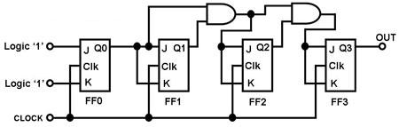
The circuit in Figure 1 is a 4-bit asynchronous counter, also known as a ripple counter. It consists of four J-K flip-flops with their J and K inputs connected to logic 1. This configuration causes the output of each...
The 1381 solar engine uses a 1381 voltage detector (a.k.a., a voltage supervisor) IC to drive a voltage-based (type 1) solar engine. The 1381 is normally used to reset CPUs and micros when the power supply drops too low...
This circuit regulates a DC power output and has a wide range of applications. It can be utilized to control the speed of a motor, a pump, a toy train, or the brightness of an LED or lamp. Essentially,...
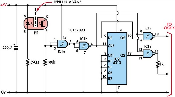
This document outlines the construction of a pendulum-controlled clock designed for high accuracy. Although it has a retro appeal, it represents an intriguing project. The project requires a spare quartz clock, which must be modified by isolating two pads...
A compact and portable 12V solar power inverter circuit designed to provide illumination. This proven design converts 12V DC from a storage battery. This 12V solar power inverter circuit is engineered to transform direct current (DC) from a solar battery...
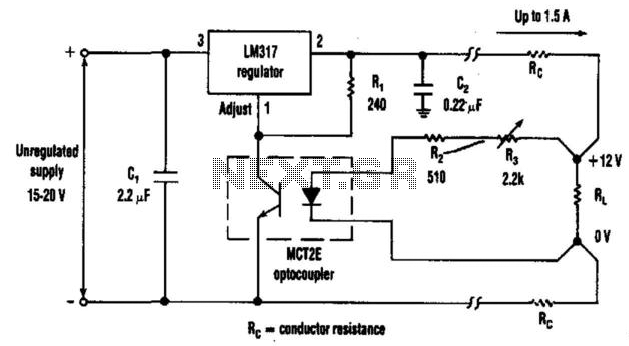
The optocoupler provides load sensing for a 3-terminal regulator, such as the LM317 series. Rl sets a current of 5 mA through the optocoupler transistor, and R3 is adjusted for 12 V across the load. The circuit utilizes an optocoupler...