
Digital code Lock with AT89C2051

The described digital lock system utilizes the AT89C2051 microcontroller, which is pivotal in managing the access control functionality. The microcontroller features an 8-bit architecture and is equipped with 2KB of ROM, allowing for the storage of the control program. The system is designed to enhance security by ensuring that only users with the correct password can gain access to restricted areas.
The password management is facilitated through an EEPROM (Electrically Erasable Programmable Read-Only Memory), which provides the flexibility to modify the stored password without requiring physical access to the microcontroller. This feature is essential for maintaining security, as it allows for regular updates to the access credentials.
A keypad interface is integrated into the system, enabling users to input their passwords. The keypad typically comprises a matrix arrangement of keys, which allows for efficient data entry. Upon entering a password, the microcontroller compares the input against the stored password in the EEPROM. If the entered password matches the stored password, the microcontroller activates a relay.
The relay serves as an electronic switch that controls the locking mechanism of the door. When the relay is energized, it allows current to flow to the locking mechanism, thereby unlocking the door and granting access to the authorized user. Conversely, if the password does not match, the relay remains deactivated, and the door remains locked, preventing unauthorized access.
To further enhance the security and functionality of the system, additional features may be incorporated. These can include visual indicators such as LEDs to signal the status of the lock (locked/unlocked) and audible alerts for incorrect password entries. Moreover, the system can be designed to include a timeout feature that temporarily disables access after a certain number of failed attempts, thus mitigating the risk of brute-force attacks.
In summary, the microcontroller-based digital lock system provides a robust solution for access control, leveraging the capabilities of the AT89C2051 microcontroller, EEPROM for password storage, and a user-friendly keypad interface to ensure secure and reliable operation in restricting access to designated areas.Security is a prime concern in our day-today life. Everyone wants to be as much secure as possible. An access control for doors forms a vital link in a security chain. The microcontroller based digital lock for Doors is an access control system that allows only authorized persons to access a restricted area. The system is fully controlled by the 8 bit microcontroller AT89C2051 which has a 2Kbytes of ROM for the program memory.
The password is stored in the EPROM so that we can change it at any time. The system has a Keypad by which the password can be entered through it. When the entered password equals with the password stored in the memory then the relay gets on and so that t 🔗 External reference
Related Circuits

All the adapted numbers of the cipher are in the aforementioned line. To set the adjustment of the cardinal of the code, we accept to set the acceptable affiliation amid the bulge of the 7414 ascribe and the adapted...
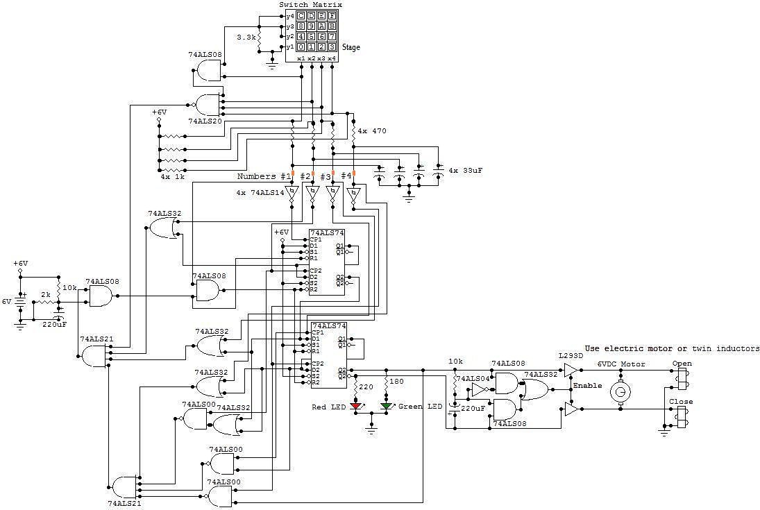
This circuit is an electronic locker that operates using a combination of switches, functioning based on a specific code. The switch matrix is located on the locker door and consists of 16 switches arranged in a 4x4 grid, totaling...
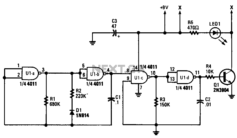
Gates U1a and U1b are configured as a low-frequency oscillator. The output waveform at pin 11 is nonsymmetrical, with the positive portion of the signal comprising only 20% of the time period. Diode D1, a 1N914 general-purpose unit, along...
The 1N4001 is a 1 Amp silicon rectifier with a voltage range of 50 to 1000 volts. It features guaranteed high-temperature soldering, high current capability, a diffused junction, low reverse leakage, and utilizes a void-free molded plastic technique for...
Utilizing a dual polarity power supply (+-5V is suitable) can resolve most clipping issues. It is necessary to consult the data sheet for the appropriate pins to connect the voltages. A dual polarity power supply is essential in many electronic...
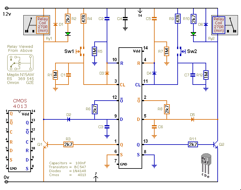
This versatile circuit offers a selection of different switching modes. It can function as two entirely separate toggle switches, with each push button successively energizing and de-energizing its corresponding relay. Alternatively, the two switches can be interconnected with diodes...