
Audio Electronic Locker Circuit Schematic Picture

The circuit design involves a coded locking mechanism utilizing a matrix of switches and an integrated circuit (IC) for processing the input. The numbers associated with the code are set in a specific line, which corresponds to the input from the switches. To adjust the code, a proper connection must be made between the output of the 7414 Schmitt trigger and the corresponding capacitor value, which helps in stabilizing the signal and ensuring reliable operation.
For instance, selecting the first row (y1) with a code of 0, 1, 2, or 3 links the first number (#1) to the top left position (x1). The transition of the code from 0 is indicative of the relationship between the x1 and y1 coordinates. These connection points are highlighted in orange in the schematic diagram for clarity.
The locking mechanism is visually indicated by two LEDs: a red LED and a green LED. When the locker is secured, the red LED illuminates while the green LED remains off. Conversely, when the locker is opened, the red LED turns off, and the green LED lights up, providing a clear visual indication of the locker’s status.
The locking action is executed by pressing any of the 16 switches arranged in a matrix configuration. This design allows for a compact and efficient user interface. The entire circuit is powered by a 6V power source, with a recommendation for using a 6V rechargeable battery. This option provides longevity, lasting at least three full days on a single charge, and is environmentally friendly due to its reusability. Alternatively, four 1.5V batteries can be connected in series to achieve the required voltage, although this setup has a shorter lifespan of approximately five hours, making it a less economical choice in the long run.
Overall, this circuit design effectively combines user interface elements with electronic components to create a functional and efficient locking system.All the adapted numbers of the cipher are in the aforementioned line. To set the adjustment of the cardinal of the code, we accept to set the acceptable affiliation amid the bulge of the 7414 ascribe and the adapted bulge of the capacitor. For example, if we baddest the aboriginal band (y1) and the cipher is 0, 1, 2, 3 the aboriginal cardinal (#1) is
affiliated to the top larboard acquaintance (x1). The about-face 0 is agnate to x1/y1. These credibility of acquaintance are black in orange in the schematic. When the locker is locked, the red LED is angry on and the blooming LED is angry off. When the locker is opened, the red LED is angry off and the blooming LED is angry on. To lock the locker, we can advance any of the 16 switches of the matrix. The locker is powered by a 6V source. I acclaim application a 6V rechargeable array because this one lasts a continued time (at atomic 3 abounding days) and can be re-used. Otherwise, we can use four 1. 5V array affiliated in serial. These atomic alone 5 hours but are beneath expensive. 🔗 External reference
Related Circuits

The TDA3567 is a monolithic integrated decoder designed for the NTSC color television standards. It incorporates all the necessary functions for the demodulation of NTSC signals. Additionally, it features a luminance amplifier and an RGB matrix amplifier. These amplifiers...

The adjustment potentiometer RP can modify the magnitude of the DC output voltage. The adjustment potentiometer, designated as RP, is an essential component in various electronic circuits, particularly in power supply systems and signal conditioning applications. It serves as a...

The digital visitor counter is a reliable circuit designed to accurately count the number of persons or visitors in a room. When an individual enters the room, the counter increments by one, and when someone leaves, the counter decrements...
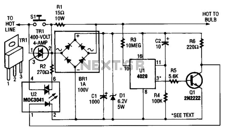
The automatic porch-light control circuit maintains a triac in an active state until a 4020 divider counts a series of 60-Hz power line pulses. This circuit is designed to turn off the light after a specified duration, utilizing pins...

The cookers pot quality detection circuit is designed to assess the quality of cooking pots. The testing process utilizes a disc lesion-induced voltage (EMF) to determine the pot's quality. The cookers pot quality detection circuit employs a method based on...
The project involves building an autofade table lamp based on a specific circuit diagram. The actual test circuit is depicted, with a note that resistor R1 from the schematic was omitted, as it was not necessary for the testing...