
Digital Compass

The digital compass circuit utilizes a four-output Hall effect sensor to detect magnetic fields and determine directional orientation. The sensor outputs are processed through a series of NOR gates, which serve to combine the four distinct outputs into eight unique states, effectively representing the eight cardinal and intercardinal directions (North, Northeast, East, Southeast, South, Southwest, West, and Northwest).
Each of the eight outputs from the NOR gates corresponds to a specific direction, illuminating an LED indicator for that direction. The LEDs are driven by inverters, which ensure that the output signal is suitable for activating the LEDs, providing a visual representation of the current heading.
The circuit is powered by a versatile power supply capable of operating within a range of 5.25 to 18 Vdc. This flexibility allows the digital compass to be integrated into various applications, from portable devices to fixed installations. The schematic design is crucial for ensuring the correct configuration of components, including the Hall sensor, NOR gates, inverters, and power supply connections, to achieve reliable performance in direction sensing.
In summary, this digital compass circuit exemplifies an efficient integration of sensor technology and digital logic to produce a user-friendly directional indicator, suitable for a wide range of electronic applications. A four output Hall sensor combined with a few logic gates produce this digital compass. The NOR gates resolve the four Hall outputs into eight distinct compass directions. LEDs to indicate direction are driven by eight inverters. A power supply for 5.25- to 18-Vdc operation is shown in the figure.
Related Circuits
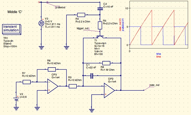
A design for a digitally controlled analog oscillator is being developed. The control voltage is generated by a microcontroller (Arduino) and is utilized through two operational amplifiers, along with a resistor and capacitor network that forms an integrator circuit....
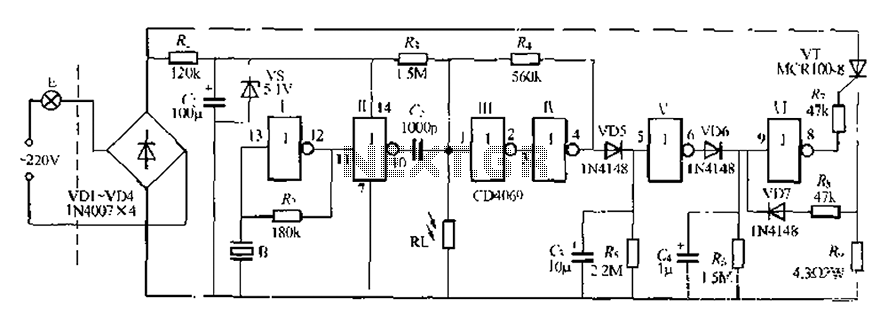
The circuit is designed for sound and light control of stairway and walkway lighting. It features high immunity and includes soft-start and over-current protection mechanisms. During the day, the photosensitive resistor has low resistance, resulting in a low voltage...
The motor is utilized to provide the mechanical output of the system and to move the potentiometer for loop closure. For high-power servos, three-phase motors can be employed. Potentiometer: A simple potentiometer can be used for standard industrial applications...

Collecting and storing experimental data presents a common challenge for hobbyists. A widely used method involves utilizing a device that converts analog data into digital format and stores the information on a computer. These devices are known as A/D...
When digital data is transmitted over long distances (greater than 1 meter), the integrity of the transfer can be compromised by parasitic effects such as ground level shifts and ground loops, in addition to extraneous noise that may be...
This circuit measures the distance covered during a walk. The hardware is housed in a small box that can be slipped into a pocket. The display is arranged such that the leftmost display, D2 (the most significant digit), shows...