Servo CDI Programmable Digital Ignition
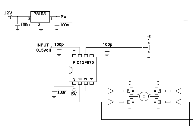
The motor is utilized to provide the mechanical output of the system and to move the potentiometer for loop closure. For high-power servos, three-phase motors can be employed. Potentiometer: A simple potentiometer can be used for standard industrial applications to determine the current position of the servo. However, for high-accuracy CNC systems, an encoder with a high pulse count is necessary. Analog controllers typically function as a "P" controller, which performs adequately if the system can maintain the current position when the motor is off. However, a "position error" occurs when a fixed force is applied to the servo, as a small error is required to generate the necessary torque to maintain its position. A PID controller addresses the "position error" using the "I" parameter and can enhance response speed for target changes with the "D" parameter. The controller reads the current position from the potentiometer or encoder, subtracts it from the target position, and determines the "error" variable. This variable indicates how far the system is from the desired position. Using the "P," "I," and "D" coefficients, the controller calculates the "control action" to be sent to the motor driver. Motor Driver: To enable bidirectional movement of the motor, an H-driver is typically utilized to reverse polarity. A PWM output is employed to control the motor's power. Additionally, for large motors, a current limitation is necessary within the driver to prevent damage to the MOSFETs or IGBTs during startup, direction changes, or when applying load to the motor. Kp represents the "proportional" coefficient of the controller. The servo can operate using only this value, with the "error" variable multiplied by it to generate the "control action." Small values result in slow movement towards the target position, while high values can induce oscillation when reaching the target. A small value can lead to significant "position error" if "Ki" is not utilized. Ki is the "integrative" coefficient, where the controller accumulates the error during operation and uses this coefficient to provide an additional "control action" to the main output. This function allows the system to reach its position even with a small Kp. A high Ki value may cause oscillation, while a small Ki value results in slow position attainment (especially with small Kp). Ki is crucial for maintaining some output at the motor when the target position is reached and additional torque is still needed (for instance, when a spring is present in a throttle body). Once the target is reached, the error becomes zero, and the proportional output will also be zero. Without an integrative function, the spring force may cause the servo to revert until equilibrium is achieved. However, with Ki in place, the system can retain some memory to maintain torque at the motor when the error is zero (indicating the target has been reached). Kd stands for the "derivative" coefficient, where the controller calculates the difference between the current and previous errors to assess system performance, multiplying this value by the coefficient to derive an additional "control action." For example, if the target is suddenly increased, this value will be high, prompting a more substantial response from the system. Conversely, if the system is rapidly approaching the target, this value will reduce motor torque. Kd should be kept small to prevent the system from behaving erratically. Dead Band: As the current position of the servo and the target are obtained by a microcontroller, inaccuracies and oscillations in readings may arise. Therefore, a small dead band is defined to ensure that when the servo is very close to the target, the motor will cease operation. Otherwise, the motor would continuously perform small pulses. Motor Offset: Motors are not linear; they do not initiate movement until a certain output voltage is reached. Consequently, a small offset is added to the PID output.
The described system integrates a motor, potentiometer or encoder, PID controller, and motor driver within a feedback loop to achieve precise control of position and torque. The motor serves as the actuator, converting electrical signals into mechanical motion. The potentiometer or encoder provides real-time feedback on the motor's position, which is essential for maintaining accuracy in applications such as CNC machining or robotics.
The PID controller plays a critical role in this system by continuously adjusting the control action based on the error calculated from the difference between the target position and the actual position. The proportional component (Kp) provides immediate response to the error, while the integrative component (Ki) addresses accumulated errors over time, ensuring the system reaches and maintains the desired position even when external forces, such as springs, are present. The derivative component (Kd) anticipates future errors based on the rate of change, enhancing the system's stability and response time.
The motor driver interfaces with the PID controller and the motor, employing PWM signals to regulate the motor's speed and direction. The H-driver configuration allows for bidirectional control, essential for applications requiring reversibility. Current limiting features within the driver protect the power components from damage during operation, particularly under load or during rapid direction changes.
Dead band settings are crucial for minimizing unnecessary motor activity when the servo is near the target position, preventing wear and tear on the motor and enhancing system longevity. The inclusion of a motor offset compensates for the non-linear characteristics of the motor, ensuring that it only responds when a sufficient control signal is present.
Overall, this comprehensive system design allows for precise control of servo motors in various industrial and automation applications, ensuring reliable performance and accurate positioning.The motor is used to provide the mechanical output of the system, and to move the potentiomer to close the loop. For high power servos three-phase motors can be used. Potentiometer: For standard industrial applications a simple potentiometer can be used to get the current position of the servo.
For high accuracy CNC systems an encoder with high number of pulses will be needed. Analog controllers usually are only a "P" controller, they work fine if the system can keep the current position when the motor is off, but they create a "position error" when a fixed strenght is applied to the servo, because the system needs a small error to get the necesary torque to keep its position. PID controller fix the "position error" with the "I" parameter, and also can increase the response speed for the target changes with the "D" parameter.
The controller reads the current position from the potentiometer or encoder, and substracts from the target position and gets the "error" variable. This variable tells the controller how far is from the desired position. By using the "P", "I" and "D" coefficients the controller gets the "control action" to be sent to the motor driver.
Motor Driver: As the motor needs to move in two directions usually a H-driver is used to reverse polarity. A PWM output is used to control the motor power. In addition with large motors a current limitation is needed inside the driver to prevent the MOSFETs/IGBTs to be damaged when starting, changing direction or appliying a load to the motor.
Kp, this is the "proportional" coefficient of the controller. The servo can work by using only this value. The "error" variable is multiplied by this value to get the "control action". Small values will cause the system to move slowly to the target position. High values will cause the system to oscillate when reaching the target position. An small value generates high "position error" if not using "Ki". Ki, this is the "integrative" coefficient. The controller accumulates the error during its normal performing, and uses this coefficient to get an addition "control action" to be added to the main output. This function causes the system to reach its position even when for small Kp. A high Ki value causes the system to oscillate. A small Ki value causes the system to reach its position slowly (for small Kp) Ki is important to get some output at the motor when the target position is reach and some torque still being needed (for example when a spring present in a throttle body).
As the target was reach, error=0, and then the proportional output will 0. If no integrative function is present, the spring force will cause the servo to go back until the equilibrium is reach. But when Ki is used, the system can have some memory to keep certain torque at motor when error=0 (target reach).
Kd, this is the "derivative" coefficient. The controller calculates the difference between the current error and the previous error to know how the system is performing, and multiplies this value by this coefficient to get an additional "control action" to be added to the previous ones. For example, if target is suddenly increased, this value will be high and will cause a higher response from the system.
And also, if the system is reaching quickly the target, this value will reduce the motor torque. Kd has to be a small value to prevent the system act as "nervous" servo. Dead Band: As current position of servo and target are acquired by a microcontroller, some unacuracy is present on the readings, and some oscillation is present on them. Thus, a small band is defined to ensure that when servo is very close to the target, the motor will stop.
In other case, the motor always will be doing small pulses. Motor Offset: motors are not linear, they won`t start to move until certain output voltage is reach. Thus a small offset is added to the PID output (when output 🔗 External reference
