Digital Delay Unit For Surround Sound
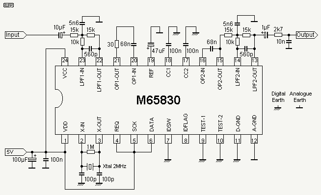
The digital delay presented here is expected to be sufficient for most applications, and although the delay is fixed at 20ms, this is the most usable delay period. This is the equivalent of being about 7 metres away from the rear speakers, and they will have a suitably distant sound, even when relatively close to the listening position.
The digital delay circuit described operates by processing an audio signal to introduce a fixed delay of 20 milliseconds. This delay is particularly useful in audio applications where synchronization between sound sources is critical. The circuit typically consists of an analog-to-digital converter (ADC) to sample the incoming audio signal, a digital signal processor (DSP) or microcontroller to manage the delay, and a digital-to-analog converter (DAC) to output the delayed signal.
In the schematic, the ADC captures the audio input, converting it into a digital format for processing. The DSP then holds the sampled data in a buffer for the duration of the delay period. Once the 20ms delay has elapsed, the DSP sends the buffered audio data to the DAC, which converts the digital signal back to an analog format for playback through the speakers.
The 20ms delay corresponds to an approximate distance of 7 meters, which helps to create a spatial audio effect, making sounds from rear speakers appear to originate from a greater distance. This effect can enhance the listening experience, particularly in home theater applications, where sound positioning is essential for immersive audio experiences.
Power supply considerations for the circuit include ensuring that the ADC, DSP, and DAC operate within their specified voltage ranges, typically requiring a regulated power supply. Additionally, filtering capacitors may be included in the power supply lines to minimize noise and ensure stable operation of the digital components.
Overall, this digital delay circuit is designed to be user-friendly, with straightforward integration into existing audio systems, making it suitable for a wide range of applications in both consumer and professional audio environments.The digital delay presented here is expected to be sufficient for most applications, and although the delay is fixed at 20ms, this is the most usable delay period. This is the equivalent of being about 7 metres away from the rear speakers, and they will have a suitably `distant` sound, even when relatively close to the listening position.
🔗 External reference
