
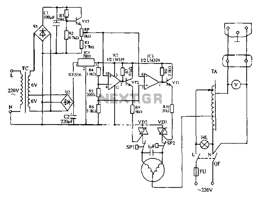
Massage digital display circuit

The display circuit in a digital massager operates by integrating a microprocessor, specifically the EM78156, which serves as the central control unit. This microprocessor is responsible for interpreting user inputs and executing control commands for the device's various functions. The manual operation instructions are processed by the EM78156, which activates two transistors that control the power supplied to the DC motor. The motor is essential for the massager's operation, providing the necessary mechanical movement.
The power supply to the motor is divided into two sets of terminals: A +, A- for one motor direction, and B +, B- for the opposite direction. This dual control allows for bidirectional movement, enhancing the massaging capability of the device. The transistors act as electronic switches, enabling or disabling the motor supply voltage based on the processed instructions from the microprocessor.
Additionally, the circuit incorporates an 8-bit register, denoted as N2, which plays a crucial role in driving the digital display. This register holds the data that corresponds to the operational status and settings of the massager, allowing for dynamic visual feedback to the user. The digital display presents various information, such as speed settings, massage modes, or operational timers, thereby improving user interaction and experience.
Overall, the integration of the EM78156 microprocessor, the transistor-driven motor control, and the 8-bit register for the display forms a cohesive and efficient electronic circuit that enhances the functionality of a digital massager.Display circuit as shown in a typical digital massager. The core of the control circuit is a microprocessor EM78156, it then received instructions manual operation of the circu it, on the one hand by triggering the two transistors to provide a DC motor supply voltage (A +, A- and B +, B-), with displacement through 8 bit register N2 digital display drive circuit.
Related Circuits
Automatic AC voltage regulator circuit The automatic AC voltage regulator circuit is designed to maintain a stable output voltage despite fluctuations in the input voltage. This circuit is essential for protecting sensitive electronic devices from voltage variations that can lead...
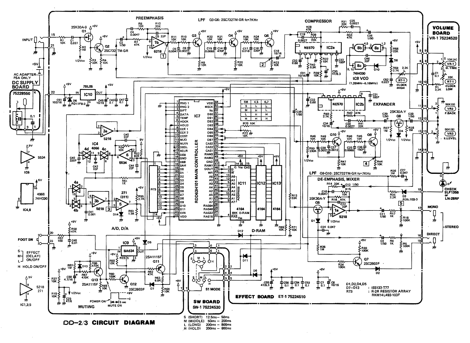
The DD-2 is a highly regarded digital delay pedal that emulates an analog sound. It was initially sold from 1983 until it was discontinued in 1986, after which it was relaunched without any modifications as the DD-3 (noting that...
There is no need to be disappointed the next time your digital camera displays a low battery indication during a picnic trip. Simply connect this digital camera adapter to the cigarette lighter outlet of your car and link the...
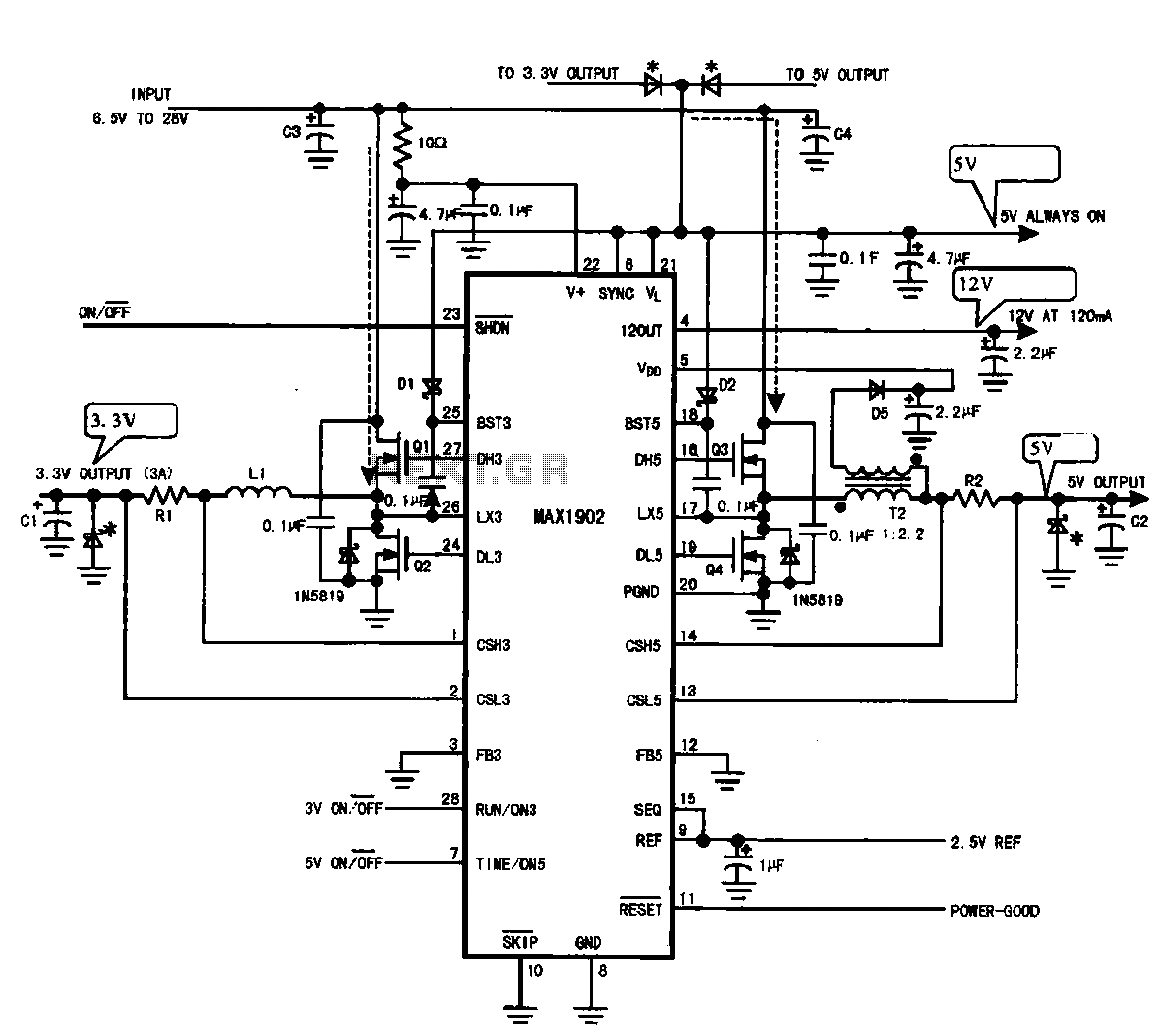
Multi-output power supply circuit (MAX1902). This circuit illustrates the power supply configuration for a notebook computer motherboard, utilizing the MAX1902 chip for power control. It is designed to convert the battery's DC voltage into multiple DC voltage outputs. The multi-output...
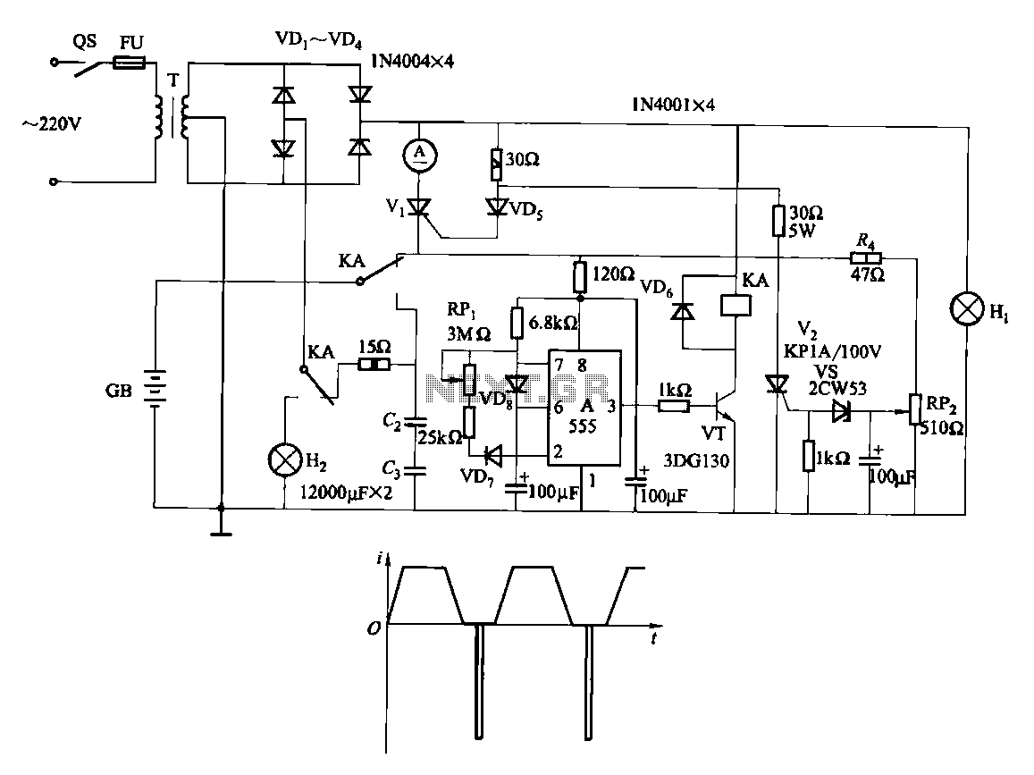
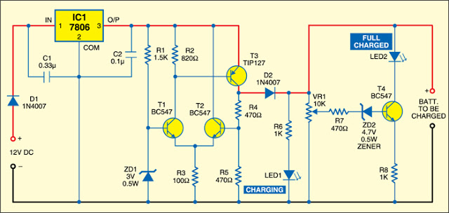
Fast and efficient charging is significantly higher than conventional charging, achieving a current charge that is ten to several times greater. When the battery voltage reaches a predetermined level (known as the polarization point), polarization within the cell becomes...
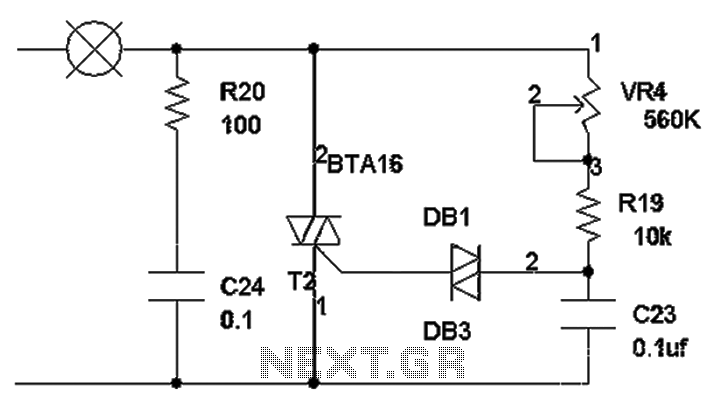
The TRIAC dimmer circuit diagram operates on the principle that a 220V lamp is controlled through the charging of capacitor C23 via resistors VR4 and R19. The charging time is influenced by the values of VR4 and R19, where...