
digital electronic lock

The digital lock circuit is designed to enhance security by requiring a specific four-digit code for relay activation. The main components include a keypad, a CD4017 decade counter, and a relay driver circuit. The keypad typically consists of a matrix arrangement of buttons, where each button corresponds to a specific digit. When a button is pressed, it sends a signal to the CD4017 counter.
The CD4017 counter is a decade counter that counts from 0 to 9. It has ten outputs, but only the first four outputs (pins 3, 2, 4, and 7) are utilized in this application. Each output corresponds to a specific digit in the code. The outputs are connected to a logic gate configuration that ensures only the correct sequence of inputs can advance the counter. This is achieved through the use of AND gates, which require multiple inputs to be high (logic level '1') simultaneously.
Once the correct sequence of digits is entered, the CD4017 counter advances to the final output, which activates the relay. The relay can then control a larger load, such as a door lock or alarm system, providing a physical mechanism for locking or unlocking based on the entered code.
To ensure reliability, debounce circuits may be implemented to filter out noise from the keypad inputs, preventing false triggering from mechanical bounce when buttons are pressed. Additionally, a reset mechanism can be integrated to reset the counter if an incorrect digit is entered, requiring the user to start over.
Overall, this digital lock circuit is a practical application of basic logic ICs and provides a straightforward yet effective method for securing access through electronic means.The digital lock shown below uses 4 common logic ICs to allow controlling a relay by entering a 4 digit number on a keypad. The first 4 outputs from the CD4017 decade counter (pins 3,2,4,7) are gated together with 4 digits from a keypad so that as the keys are depressed in the correct order, the counter will advance..
🔗 External reference
Related Circuits
Finally I was able to control an LCD Hitachi display and a 12-key matrix keypad with only one 16F84 or 16F628. In a near future, I will be able to control a full QUERTY-type keyboard and a LCD display....
The analog to digital sketches have been extensively covered using various components. To progress to more complex circuits and concepts, it is essential to understand these simpler ones. This tutorial will not delve as deeply as others due to...
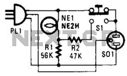
If residing in a cold climate, it is reassuring to confirm the functionality of an engine-block heater. This device indicates whether the heater is operational. To use, connect PL1 to a power outlet; the NE1 indicator should illuminate. Next,...
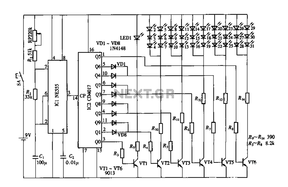
An electronic decorative peacock consists of 10 light-emitting diodes (LEDs), each of which contains multiple LEDs arranged in the tail of the peacock model. The light emission drive circuit operates the fan-shaped LEDs in a cyclic manner, emitting light...
A clock-controlled relay, also known as a time delay relay, allows for the automatic activation of a load, such as a water pump, at a predetermined time. This device utilizes a standard clock mechanism to trigger the circuit, enabling...

The goal of Advanced Digital Electronics courses is to connect basic logic gates (combinational circuits) with technical subjects related to binary counter topologies (both Asynchronous and Synchronous), shift registers, memory, and Digital Signal Processors (DSP), which are categorized as...