
Clock Controlled Relay

The clock-controlled relay circuit typically consists of several key components: a clock module, a relay, a power supply, and the load (in this case, the water pump). The clock module, which can be a digital or analog timer, is responsible for keeping track of time and determining when the relay should be activated.
Upon reaching the specified time, the clock module sends a signal to the relay. The relay acts as an electrically operated switch, allowing current to flow to the load when activated. In this configuration, the relay can handle higher voltage and current levels, making it suitable for controlling devices like water pumps, which may require more power than the clock module can provide directly.
The power supply is crucial for ensuring that both the clock module and the relay operate correctly. It must be rated to provide adequate voltage and current for all components in the circuit. Additionally, protective features such as diodes may be included to prevent back EMF from damaging the relay or clock module when the load is switched off.
To enhance the functionality of the circuit, it may be designed with adjustable time settings, allowing users to customize the activation time according to their specific needs. This flexibility makes clock-controlled relays ideal for various applications, including irrigation systems, aquariums, and automated home systems, where precise timing for device activation is essential.
Overall, the clock-controlled relay circuit is a practical solution for automating the operation of electrical loads based on time, improving efficiency and convenience in various settings.You can switch on a load such as Water pump automatically at the required time through this Clock Controlled Relay or also known as Time Delay Relay. It uses an ordinary clock to trigger the circuit to switch on the load 🔗 External reference
Related Circuits
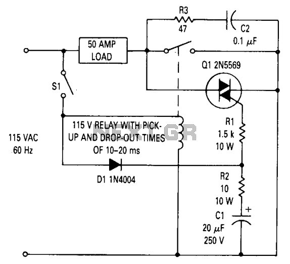
This circuit can be utilized to prevent relay contact arcing for loads up to 50 amperes. A delay exists between the moment a relay coil is energized and when the contacts close, as well as a delay from when...
This project involves using an EasyDriver stepper motor driver and a 1.8-degree per rotation stepper motor to achieve a motor speed of one revolution per minute. The EasyDriver simplifies the operation, requiring a DC voltage of 7-30V connected to...
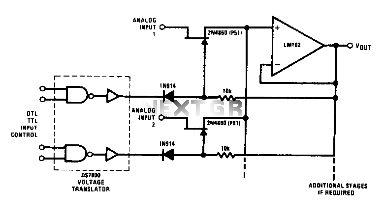
This analog switch utilizes the 2N4860 JFET, which features a low on-resistance of 25 ohms and minimal leakage current. The LM102 is employed as a voltage buffer in the circuit. Additionally, this configuration can be modified for use in...
Propclocks are complex devices that utilize a PIC microcomputer operating at 10 MHz. The PIC serves as the core component, managing the timing of LED illumination to create the illusion of numbers and, in analog mode, hands suspended in...
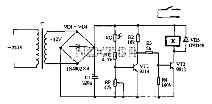
The circuit operates on 220V AC input, which is transformed to approximately 12V DC using a step-down transformer (T), a diode bridge rectifier (VDI-VD4), and a filter capacitor (C1). This setup is designed to power the entire circuit. The...
This circuit is designed to serve as a programmable LED display for various applications. It features an 8 x 32 LED dot matrix interfaced with a Xino (or Arduino). In addition to the display, the circuit includes two buttons...