
Control 7 segment LED displays with AVR

LED displays are widely utilized in various applications, ranging from digital clocks and scoreboards to more complex information panels. Each LED in the display can be individually controlled, allowing for the creation of numbers, letters, and custom symbols depending on the configuration of the diodes. When designing a circuit for driving multiple LED displays, it is essential to consider the microcontroller's output capabilities, as each additional display will require more pins for control.
To implement dynamic control, a multiplexing technique is often employed. In this method, the displays are connected in such a way that only one display is activated at any given moment. A microcontroller can cycle through the displays rapidly, turning each on for a brief period while the others remain off. This rapid switching takes advantage of the persistence of vision effect, where the human eye perceives a continuous image rather than discrete flashes of light.
The circuit typically includes a microcontroller, resistors for current limiting, and transistors or MOSFETs for switching the displays on and off. The microcontroller will execute a program to control the timing and sequence of the displays, ensuring that each one is illuminated long enough for the eye to perceive the information clearly. The use of multiplexing not only conserves microcontroller pins but also reduces power consumption, as only one display is powered at a time.
In summary, LED displays are effective tools for visual communication, and their operation can be efficiently managed through dynamic control techniques such as multiplexing. This approach allows for the display of complex information while optimizing the use of available microcontroller resources.LED displays are nothing more than sets of Light Emitting Diodes. The difference is that they have different shapes in order to display specific information. So driving LED displays is the same as regular LEDs. This is simple connection when there are enough of microcontroller Pins. But if you want to connect more displays you will need more micro controller pins than it can give you. Then you need to make more advanced circuit with dynamic control. The idea of this circuit is very simple. Human eye is inertial and can`t notice fast flicker of images. Thus you need to light only one display at one time, and then switch to another and so on. Refreshing displays like 10 15 times a second should be enough to see clear image of all digits. We aim to transmit more information by carrying articles. Please send us an E-mail to wanghuali@hqew. net within 15 days if we are involved in the problems of article content, copyright or other problems. We will delete it soon. 🔗 External reference
Related Circuits
Martin Ustek has modified the project to include a Sokoban game. Information about his version can be found throughout this page; for full details, please visit his website (Czech). Either game can be selected with a menu that appears...
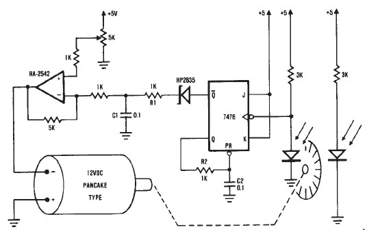
A simple encoder circuit for a DC motor can be constructed using this circuit diagram. The system consists of the HA-2542, a small 12-V DC motor, and a position encoder. During operation, the encoder generates a series of constant-width...
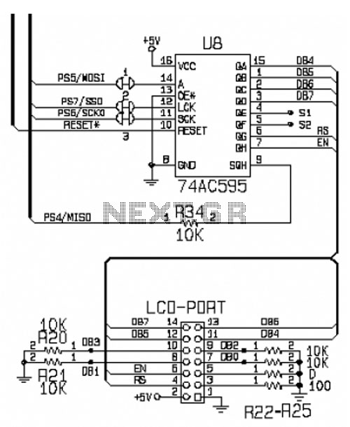
This circuit is designed for interfacing an I/O keypad and an LCD, allowing students to gain hands-on experience with basic I/O device interfacing using the HCS12 microcontroller mounted on the CML12S-DP256 development board. The keypad utilized in this circuit...
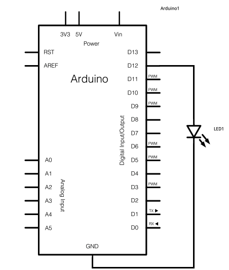
The schematic for this project consists of adding a single 5mm LED to one digital output port on the Arduino. The main components in the schematic include the Arduino Uno, a 5mm LED, and a USB cable. The left...
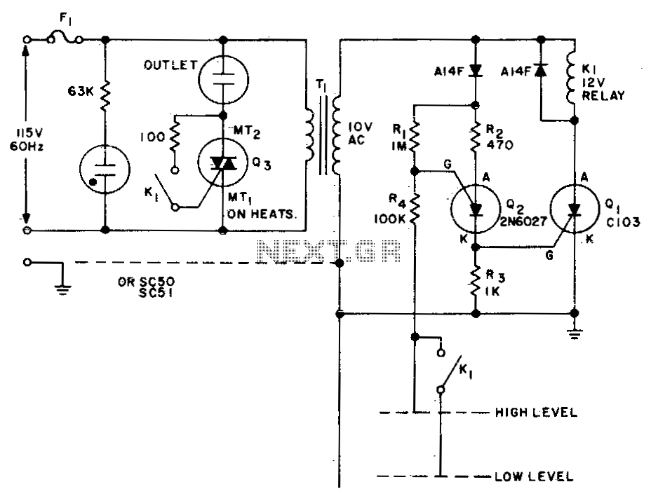
This circuit is designed to maintain the fluid level of a liquid between two predetermined points. It features two operational modes for either filling or emptying the container, which can be achieved by simply reversing the connections of relay...
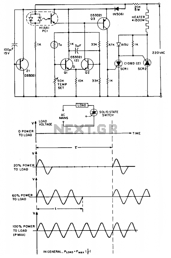
The "zero voltage switching" technique is commonly utilized to modulate heating and similar types of AC loads, where the time constant associated with the load (ranging from tens of seconds to minutes) is sufficiently long to allow smooth proportional...