
Digital lighting controler PIC16F870

The dimming pack controls the power coming out by employing phase angle control of the mains.
The schematics show the circuit used for the main board. The display board is shown here with an explanation here.
The code in the PIC is here and explained here.
The labels for the outside of the box.
The Eagle generated schematics, assembly code, and hex file are all contained within the Zip File here.
Update Oct 2003 - Circuit diagram problem found; please add a 10K resistor from each analogue input to the PIC to ground. This is required to discharge the internal capacitor in the PIC A2D. The circuit diagram has been updated.
Update Nov 2003 - New circuit diagram drawn with Eagle schematics added and new assembly code added with basic/advanced display option.
Also to come soon - A 12-channel based lighting control based in a 19" rack unit with LCD display.
The circuit is designed to interface with DMX 512 data and an analogue input voltage ranging from 0V to 10V, allowing for precise control over lighting systems. The phase angle control method modulates the power delivered to the connected loads, effectively dimming the lighting fixtures based on the input received from the DMX or analogue sources. The system features four independent output channels, enabling the control of multiple lighting fixtures simultaneously.
The microcontroller at the heart of the system, the PIC16F870, operates at a clock speed of 20 MHz, ensuring efficient processing of incoming data and control signals. The configuration of the DMX address is facilitated through a series of dip switches, allowing users to set addresses ranging from 1 to 512, which is standard for DMX systems.
The 7-segment display provides real-time feedback to the user, displaying critical operational information such as the current mode of operation, the DMX base address, and the selected preset. This interface enhances usability and allows for quick adjustments during operation.
The design incorporates three distinct modes of operation: Digital Lighting Data, Analogue Lighting Data, and Internal Presets, which can be programmed and stored for future use. The inclusion of three dimming curves—Linear, S Curve, and Switch—provides flexibility in how the lighting responds to control signals, accommodating various lighting effects and user preferences.
Updates to the design have addressed potential issues, such as the addition of a 10K resistor for each analogue input to ground, which is essential for discharging internal capacitors within the PIC's ADC, ensuring accurate readings. The latest circuit diagrams and assembly code have been refined and are available for reference, ensuring that users have access to the most current design specifications.
Future enhancements are anticipated, including a 12-channel lighting control system housed in a 19" rack unit, further expanding the capabilities of this lighting control technology.This unit recieves DMX 512 data and Analogue (0- 10v) data and uses these to phase angle control mains output. Features: DMX 512 data Input. Analogue (0- 10v )DC Input. 4 Output channels. Remotley programmable Interally saved Presets. 3 Modes of operation Digital Lighting Data, Aanlogue Lighting Data and Internal Presets. 3 Dimming Curves ( Linear , S Curve and Switch ). DMX recieve address set on Dip switches from 1 - 512. 7 seg Display shows operation mode, DMX base address and preset being used. Designed to operate on 240Vac @ 50Hz. Auto tracks mains frequency. The Designed is based on the microchip Pic device. The Pic used is the 16F870 a 28 Pin device. running at 20Mhz. The dimming pack controls the power comming out bu enploying phase angle control of the mains. The schematics shows the circuit used for the main board, The display boardis shown here with an explanition here. The Code in the Pic is here and Explained here. The Labels for the outside of the box The Eagle generated Schamatics, Asembley code and Hex file are all contained with in the Zip File Here .
Update Oct 2003 - Circuit Digram problem found please add a 10K resistor from each Analogue input to the Pic To Ground. This is required to discharge the internal capasistor in the PIC A2D the Cicruit Diagram has been updated.
Update Nov 2003 - New circuit Diagram Draw with Eagle schematics added and new Asembley code added with basic / Advaranced display option. Also To Come soon - A 12Channel Based Lighting Control Based in a 19" Rack unit with LCD display. 🔗 External reference
Related Circuits
In some cases, a cogwheel input is necessary for voltage measurement. By utilizing a single operational amplifier, an adapter can be created to accommodate a differential input for a ground-referenced voltmeter. It is recommended to use 1% tolerance metal...
By utilizing a reverse binary counter along with a binary-coded decimal (BCD) decoder, a step voltage can be generated, which can then be approximated to produce a sine wave signal with adequate accuracy for various applications. In the digital...
This is an easy to build, but nevertheless very accurate and useful digital voltmeter. It has been designed as a panel meter and can be used in DC power supplies or anywhere else it is necessary to have an...
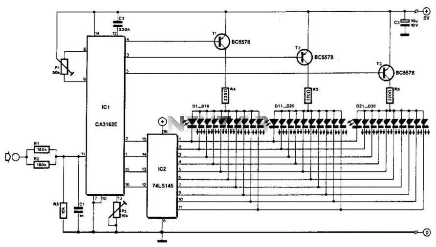
The voltage to be measured is digitized in an analog-to-digital (A/D) converter and then displayed in three decimal digits. The display consists of three groups of 10 LEDs. The meter can only be used for measuring direct voltages. The...
This circuit is designed to digitally adjust the volume of an analog audio signal. It employs a single AVR microcontroller to generate a pulse width modulated (PWM) signal for control. The innovation of the circuit lies in the utilization...
There is no need to be disappointed the next time your digital camera displays a low battery indication during a picnic trip. Simply connect this digital camera adapter to the cigarette lighter outlet of your car and link the...