
Digital Led Voltmeter

The described circuit employs an analog-to-digital converter (A/D) based on the CA3162T, which is designed for precise measurement of direct voltage levels. The converter's full-scale deflection (FSD) is originally set to 999 mV, which is suitable for low-voltage applications. To accommodate higher voltage measurements, a potential divider is implemented using resistors R1, R2, and R3. This configuration allows the circuit to extend its measurement capability to a maximum of 10 V by scaling down the input voltage appropriately.
The output of the A/D converter is represented on a display comprised of three groups of 10 light-emitting diodes (LEDs). Each group corresponds to a specific digit in the measured voltage value. The first group (D1 through D10) displays the unit's place, the second group (D11 through D20) represents the tens place, and the third group (D21 through D30) indicates the hundreds place. This arrangement provides a clear and straightforward visual representation of the measured voltage.
To ensure accurate readings, the circuit includes a nulling feature facilitated by potentiometer P1. When the input is disconnected, the circuit is adjusted to display zero volts, indicated by the illumination of the first LEDs in each group (D1, D11, and D21). The design also incorporates a calibration mechanism; after applying a known reference voltage, potentiometer P2 is adjusted to align the LED display with the expected voltage level.
The circuit is designed to handle specific operational conditions. If the measured voltage exceeds the maximum input range, the display will deactivate to prevent damage or erroneous readings. Additionally, the circuit is not capable of measuring negative voltages, as indicated by the non-illumination of the unit LEDs under such conditions. It is important to note that fluctuations in the supply voltage can adversely impact the accuracy of the measurements, necessitating stable and regulated power supply conditions for optimal performance. The voltage to be measured is digitized in an analog-to-digital (A/D) converter and then displayed in three decimal d igits. The display consists of three groups of 10 LEDs. The meter can only be used for measuring direct voltages. The A/D converter is based on CA3162T which can process direct voltage up to 999 mV (1-V full-scale deflection—FSD). The FSD is extended to 10 V with the aid of potential divider R1/R2/R3. Other ranges are possible by altering the values of the resistors. The measured value is read from three bars of LEDs: the first one of these, Dl through D10, shows units; the second, Dll through D20 tens; and the third, D21 through D30, hundreds.
The circuit is nulled with PI when the input is open. Zero here means that diodes Dl, Dll, and D21, light. Diodes D10, D20, and D30, represent the figure 9. Next, a known voltage is applied to the input and P2 is adjusted until the LEDs read the correct value. When the input voltage is too high, the display goes out. When the input is negative, the unit LEDs do not light. Notice that variations in the supply voltage affect the measurement adversely.
Related Circuits
The digital lock shown below uses 4 common logic ICs to allow controlling a relay by entering a 4 digit number on a keypad. The first 4 outputs from the CD4017 decade counter (pins 3,2,4,7) are gated together with...
When the microphone detects a loud sound, this circuit will activate the LED. The charge pump section includes a 100nF capacitor, a 10kΩ resistor, a signal diode, and a uF capacitor. The circuit operates by utilizing a microphone to sense...
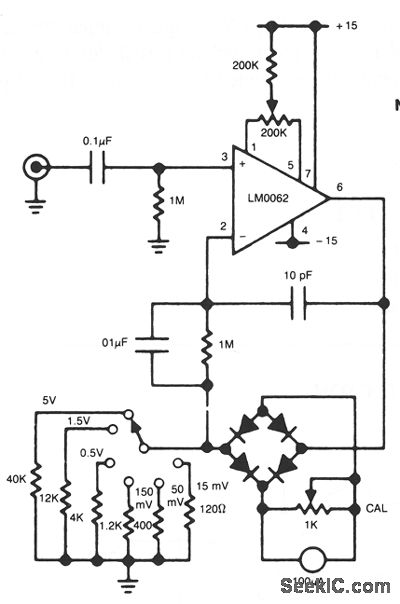
This circuit utilizes a diode bridge as a meter rectifier. The offset voltage is compensated by an operational amplifier, as the bridge is integrated within the feedback network. The circuit employs a diode bridge rectifier, which consists of four diodes...
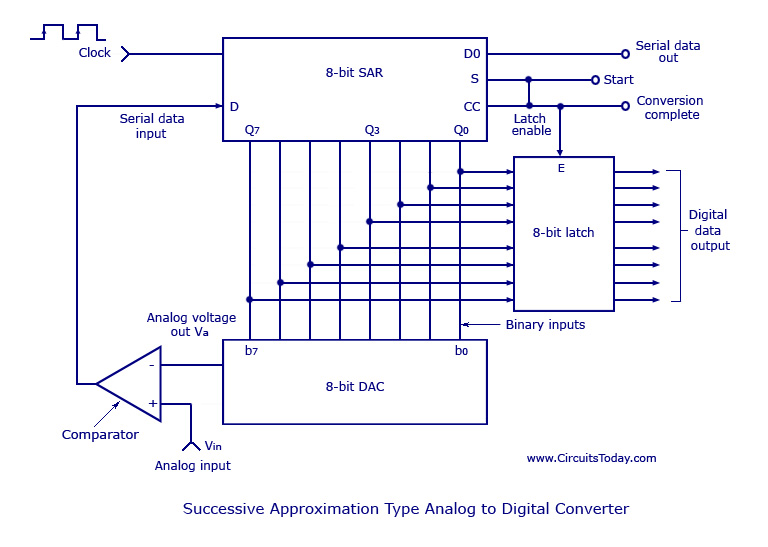
Analog to Digital Converters - Successive Approximation Type Analog to Digital Converter, working, circuit diagram. The Successive Approximation Register (SAR) Analog to Digital Converter (ADC) is a widely used type of ADC that converts an analog signal into a digital...
The high durability of a light-emitting diode (LED) makes it suitable for ON/OFF indicator applications. However, there are limitations regarding low operating voltage. Light-emitting diodes (LEDs) are semiconductor devices that emit light when an electric current passes through them. Their...
Here is the schematic, PC board pattern, and parts placement for a "Fantastic Atom Expander". This circuit produces an "exploding atom" effect using 98 LEDs. The LEDs can be any colour but blue. For a very interesting effect, make...