
Digital Radar Speedometer Circuit

The Digital Radar Speedometer circuit is designed to provide accurate speed measurements through laser technology. The system comprises a laser LED that emits a coherent light beam, which is directed toward the target vehicle. The reflected light is captured by a laser diode, which is sensitive to the wavelength of the emitted light, ensuring reliable detection. The design emphasizes the importance of maintaining a clear line of sight and appropriate distance for optimal performance, as the effective range is limited to 90 meters.
The circuit utilizes TTL logic components from the 74AS series, ensuring rapid processing of the reflected signal. This rapid response is crucial for accurately calculating the speed of fast-moving vehicles. The speedometer's display unit is designed to show speeds in a user-friendly three-digit format, with an overload indicator to alert users when the speed exceeds 999 km/h. The inclusion of a timer function allows the display to revert to zero after three seconds, preventing confusion after the speed measurement has been taken.
Power management is facilitated by a 9V battery and an SPST switch, allowing the user to easily turn the device on and off. The positioning of the display and overload indicator is ergonomically designed for easy visibility during operation. Overall, this circuit represents a sophisticated yet practical approach to measuring vehicle speed, leveraging laser technology and advanced electronic components for reliable performance.This circuit is use to Digital Radar Speedometer. It allows us to evaluate the speed of any object moving, especially cars and other vehicles. The speed is calculated in kilometers per hour (KPH). Its display has three digits. This radar works with the laser reflection. It sends laser radiation to the object and this object reflects the laser radi ation to the radar. To evaluate the speed of a vehicle, we must be in front of it. In other words, the vehicle must come in our direction. Here`s the figure of the circuit; The laser LED can send a spot of light to a distance of 90 m (295 ft). It`s very important that the distance range of the laser LED is 90 m, if not, the speed will not be calculated properly.
The laser diode, which receives the light signal by the laser LED, must be able to detect the light which is same color as that emitted by the laser LED. The laser diode and the laser LED must be placed one beside the other. They are protected by a tinted pane. They must be placed at the front of the radar and point the outside. The radar is powered by a 9V battery and it has a SPST switch to control its power state. The display, or the speed indicator, is placed at the rear of the radar, just on the right of the overload LED indicator.
All the logic components of the circuit must be of the 74AS series and TTL type. Because they have short time of response (less than 1. 7 ns) and have high frequency supports (more than 200 MHz). The radar can evaluate the speed of an object moving between 0 to 999 km/h. After this speed, the overload LED indicator will turn on and the "999" will still displayed. The radar displays the speed during 3 seconds, after this time, it displays "zero" (0). 🔗 External reference
Related Circuits
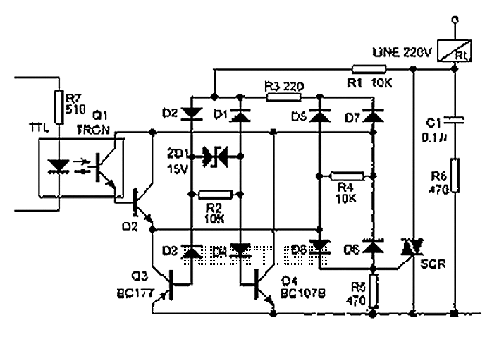
The relay illustrated in the figure operates based on non-inductive analog circuit theory. Its working principle involves a 220V power supply connected to a load (RL), resistors (R1, R3, R6), diodes (D1 to D8), and a zener diode (ZD1)....
The circuit automatically lights a bulb upon the arrival of a telephone ring and simultaneously mutes the audio from the music system or TV while the telephone handset is off-hook. The lighting of the bulb not only indicates an...
The decision to use electric power was made due to its quieter operation, lack of odor, and ease of carrying the bike up a flight of stairs. The selected conversion kit is manufactured by Currie. Although factory service is...

This is an automatic light dimmer circuit that eliminates the need for manual adjustment of light levels. It utilizes a Light Dependent Resistor (LDR) to detect ambient light conditions, which in turn controls a Triac to adjust the brightness...

This circuit utilizes digital techniques to implement the frequency-inversion algorithm by digitizing the audio, inverting the sign of every alternate sample, and performing D/A conversion on the resulting data. The outcome is an inverted frequency spectrum. Additionally, the circuit...

The circuit illustrated here demonstrates that, despite advancements in components and technology, it remains possible to design effective and intriguing circuits. This design utilizes two well-known transistors, the BF256C and the BF494. Along with the necessary resistors and capacitors,...