
Telephone line based audio muting and light on circuit

The circuit operates by utilizing an opto-coupler (IC1) to detect the ringing signal from the telephone line. When the telephone rings, the opto-coupler activates, allowing current to flow through capacitor C1, which charges and maintains the voltage necessary to keep transistor T1 in a forward-biased state. This action energizes the relays responsible for controlling the light and muting the audio devices.
Relay RL1 is responsible for turning on the bulb, providing a clear visual cue for incoming calls. The relays RL2 and RL3 serve to interrupt the audio signals from the TV and music system, respectively. The design allows for the use of a DPDT relay for systems with dual speakers, ensuring that both channels of audio are muted effectively.
The inclusion of diode D1 serves a critical protective function, ensuring that the voltage across the built-in diode of IC1 remains within safe limits during ringing conditions. This is essential for the longevity and reliability of the circuit.
The circuit's operation is designed to be seamless, with the relays remaining energized as long as the handset is off-hook, providing uninterrupted functionality until the call is completed. The design is efficient, utilizing a combination of capacitive and resistive elements to maintain control over the circuit's operation while ensuring safety and reliability during use.The circuit would automatically light a bulb on arrival of a telephone ring and simultaneously mute the music system/TV audio for the duration the telephone handset is off-hook. Lighting of the bulb would not only indicate an incoming call but also help in locating the telephone during darkness.
On arrival of a ring, or when the handset is off-hook, the inbuilt transistor of IC1 (opto-coupler) conducts and capacitor C1 gets charged and, in turn, transistor T1 gets forward biased. As a result, transistor T1 conducts, causing energisation of relays RL1, RL2, and RL3. Diode D1 connected in anti-parallel to inbuilt diode of IC1, in shunt with resistor R1, provides an easy path for AC current and helps in limiting the voltage across inbuilt diode to a safe value during the ringing.
(The RMS value of ring voltage lies between 70 and 90 volts RMS. ) Capacitor C1 maintains necessary voltage for continuously forward biasing transistor T1 so that the relays are not energised during the negative half cycles and off-period of ring signal. Once the handset is picked up, the relays will still remain energised because of low-impedance DC path available (via cradle switch and handset) for the in-built diode of IC1.
After completion of call when handset is placed back on its cradle, the low-impedance path through handset is no more available and thus relays RL1 through RL3 are deactivated. As shown in the figure, the energised relay RL1 switches on the light, while energisation of relay RL2 causes the path of TV speaker lead to be opened.
(For dual-speaker TV, replace relay RL2 with a DPDT relay of 6V, 200 ohm. ) Similarly, energisation of DPDT relay RL3 opens the leads going to the speakers and thus mutes both audio speakers. Use NC` contacts of relay RL3 in series with speakers of music system and NC` contacts of RL2 in series with TV speaker.
Use NO` contact of relay RL1 in series with a bulb to get the visual indication 🔗 External reference
Related Circuits

To enable a line-following robot to identify the line, it is essential to first detect the line itself. Several methods can be employed to distinguish a black line on a white background, or vice versa. One effective approach is...
This compact circuit enables automatic recording of phone conversations. It connects to the phone line, the microphone input of a tape recorder, and the remote control jack of the recorder. The circuit detects the voltage level in the phone...
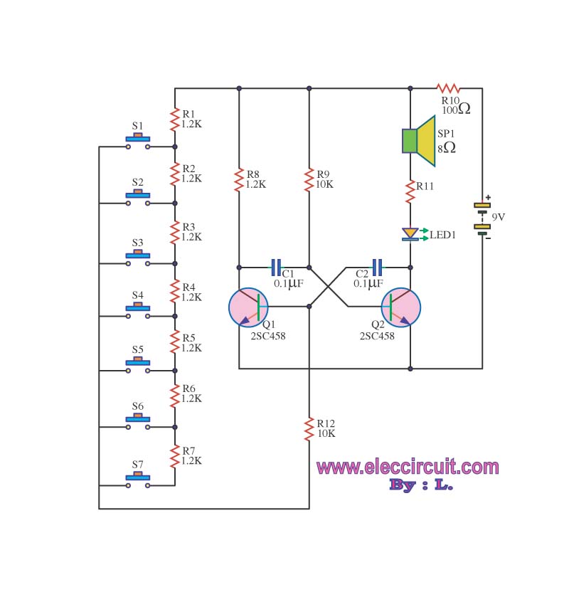
The circuit operates as an astable multivibrator, generating a square wave signal at a specific frequency. When powered, the circuit will function continuously. The astable multivibrator circuit is a type of oscillator that produces a continuous square wave output without...
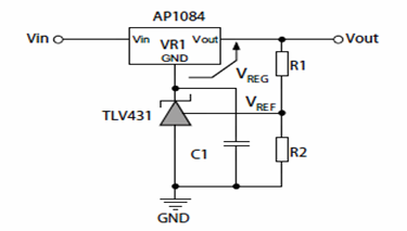
The following schematic illustrates the method for increasing the output voltage of a fixed linear regulator circuit using 3-terminal shunt regulators or references. These 3-terminal shunt regulators enhance the functionality of medium accuracy linear regulators, transforming them into precision...
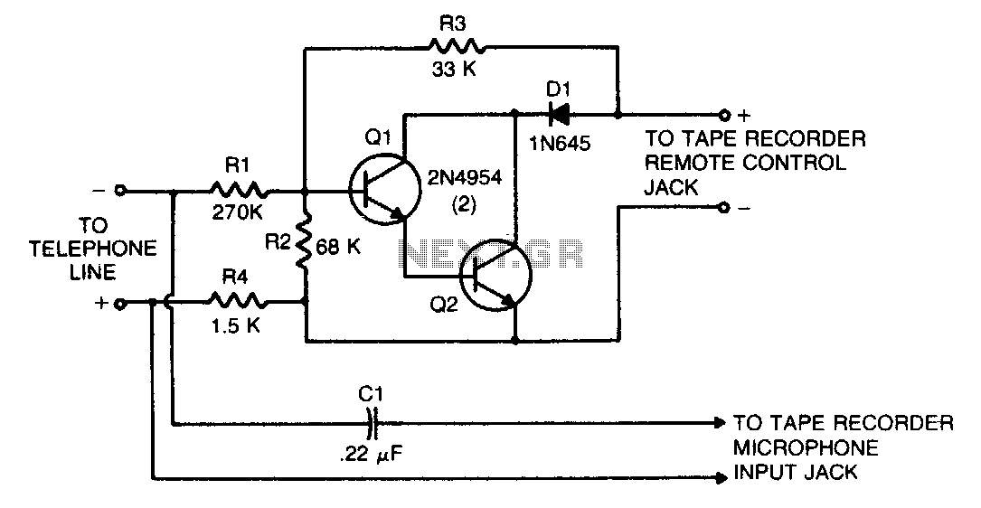
This circuit transforms a tape recorder into a fully automatic device for recording telephone conversations without requiring an external power source. The voltage at the switch terminals of the tape recorder is applied to a pair of Darlington-connected transistors,...

The excitation device for a light-duty synchronous motor rated at 625 kW has been initiated. The triggering circuit of the device consists of three identical RC phase-shift flip-flops. Adjustment potentiometers RP3 to RPs are used to set the RC...