
Digital Ramp ADC

The stairstep-ramp or counter A/D converter operates on the principle of comparing an analog input voltage to a series of discrete voltage levels generated by a digital counter. The output of the converter is a digital representation of the analog input, which is achieved through a stepwise approximation method.
In its operation, the counter A/D converter uses a clock signal to increment a binary counter. This counter produces a series of voltage levels that correspond to the binary values of the counter. The analog input voltage is then compared to these generated voltage levels using a comparator. When the analog input voltage surpasses a specific level, the comparator triggers the counter to stop incrementing, and the current binary value is output as the digital representation of the analog input.
One of the advantages of this type of converter is its simplicity and ease of implementation. However, it is important to note that the stairstep-ramp converter has several drawbacks. The primary limitation is its speed; the conversion time can be relatively long, especially for high-resolution applications, as it must count through all the discrete voltage levels. Additionally, the accuracy of the conversion can be affected by factors such as noise and the precision of the reference voltages used in the comparison process.
In practical applications, the counter A/D converter is often used in scenarios where speed is not the primary concern, such as in instrumentation and data acquisition systems. Understanding its operational characteristics and limitations is essential for selecting the appropriate A/D conversion technique for specific applications.Also known as the stairstep-ramp , or simply counter A/D converter, this is also fairly easy to understand but unfortunately suffers from several.. 🔗 External reference
Related Circuits
A digital multimeter is a highly versatile instrument that integrates multiple measurement functions within a single unit. Typically, a multimeter encompasses the functionalities of a variable-range ohmmeter, voltmeter, and ammeter, with some models also capable of testing diodes and...

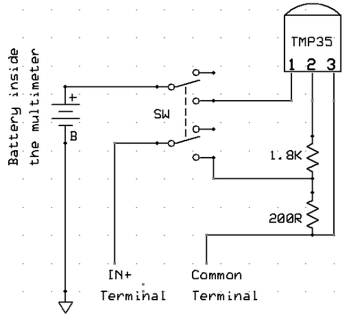
This digital thermometer circuit diagram utilizes a common 1N4148 diode as the temperature sensor. The diode's temperature coefficient of -2 mV/°C is leveraged to create an accurate electronic thermometer. A digital multimeter is employed to display the measured temperature,...
This is an easy-to-build yet highly accurate digital voltmeter designed as a panel meter. It can be utilized in DC power supplies or any application requiring precise voltage readings. The circuit uses the CL7107 Analog to Digital Converter (ADC)...
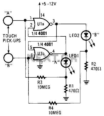
Only one LED can be illuminated when the circuit is at rest. The illuminated LED is determined by the touch pick-up that last had human contact. Pickup terminal A controls the on condition of LED1, while terminal B controls...
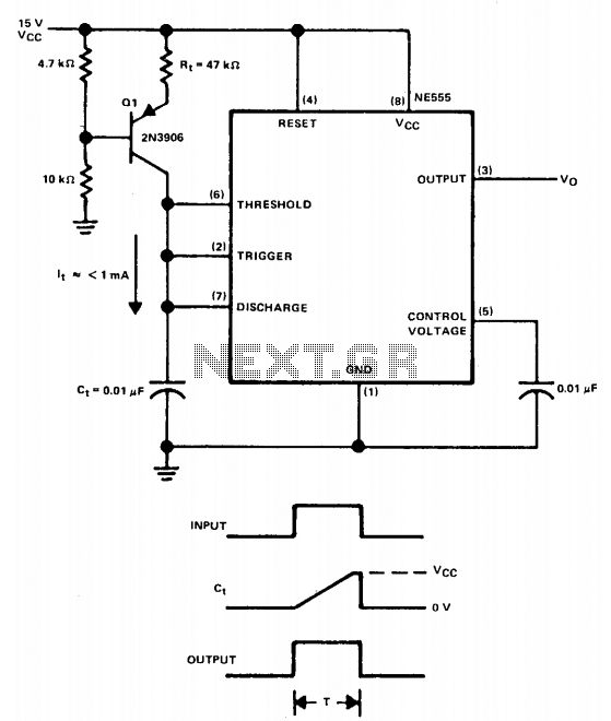
The linear charging ramp is particularly beneficial in applications requiring linear voltage control. Potential uses include long-duration voltage-controlled timers, voltage-to-pulse width converters, and linear pulse width modulators. Q1 acts as the current source transistor, providing a constant current to...
The circuit consists of a frequency modulated oscillator, an audio preamplifier with pre-emphasis to supply the frequency modulating signal, and a buffer amplifier to drive the antenna connector. Oscillator's frequency is determined by L1 resonating with the 10 pF...